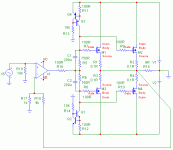
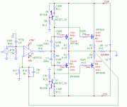
See dynamp schematics at http://www.ronybc.8k.com
I build this amplifier and it sounds not bad. I likes to know... is there anything fundamentally wrong with an opamp+mosfet design..? or this particular design...? Why such designs are not so often used arround..?
If someone have an oscilloscope and dare to build this amp then please tell me whether there is any imperfections with the output waveform.
Any suggestions..?
There have been many amps using opamps and bipolar outputs. As time went by the MOSFET came along and so did cool Power Amp IC's . I guess from the early 80's ( Hitachi HA1397 etc).
So today you could make a power amp with higher rail voltages
( higher output) and very low parts count . Maybe that's why opamp driven output stages are not around. They do have a supply voltage limitation which sometimes could be worked around. It would however make things more complex.
You must have come across the few dedicated high voltage 'driver' IC's meant for use with power output stages.
Possibly makes the standard opamp plus power output stage less attractive.
Cheers.
semiconductors: OPA552AP/IRFP240 (Farchild]/IRFP9240 (I.R.)/TL431
R+C: 7 + 10
PSU: +/- 28V,
gain: +41V/V
load: 4 Ohm
quiscent current:120mA
THD+N: 0.008% (22Hz to 22kHz, P =1 to 10W)
THD+N: 0.014% (22Hz to 22kHz, P = 11 to 40 W)
THD+N: 0.6% (22Hz to 22kHz, P = 41 to 75W)
SR: +22/-18V/us
Can your amp offer more?
R+C: 7 + 10
PSU: +/- 28V,
gain: +41V/V
load: 4 Ohm
quiscent current:120mA
THD+N: 0.008% (22Hz to 22kHz, P =1 to 10W)
THD+N: 0.014% (22Hz to 22kHz, P = 11 to 40 W)
THD+N: 0.6% (22Hz to 22kHz, P = 41 to 75W)
SR: +22/-18V/us
Can your amp offer more?
mandat,
whom do you address your post to?
If it's me, then:
Regarding power - not, as the amp shown is limited by supply voltage of opamp. In case you use OPA445 as the opamp, then yes, as supply voltage of OPA445 is up to +/-45V.
Regardind distortion - this would be more or less the same.
The amp I displayed is a class A amp and needs pretty good heatsinking. And it was shown only as an example of workable amp, contrary to the first post of this thread.
Keep cool,
Pavel
Your circuit can only drive the output to the rails, less the Vgs of the FET.
With a ±15V supply for most opamps that will be on the order of ±10V peak-to-peak into the load, or about 6W at 8 ohms.
http://patft.uspto.gov/netacgi/nph-...0&s1=4467288.WKU.&OS=PN/4467288&RS=PN/4467288
Then click on 'images' (see the FAQ if you need a TIFF viewer)
This circuit only need provide the Vgs voltage to get the full ±V from the FETs, with ±100V on the FETs you can get 500W/8R, 800W/4R, 1200W/2R, only limited by the current of your supply and how many FETs you use.
There are many fine opamps intended to drive 50R co-axial cable that will drive many pairs of FETs.
Only one ±15V supply is needed for the opamps, it could also be shared with a preamp and tone circuits.
Each power amplifier output will require its own transformer winding.
Acoustat/Hafler/Fosgate are built this way.
QSC uses BJT with driver transistors and this same scheme.
Ron (bc),
I seems to me that your T1 is cut off on positive output swings. It takes some time for the opamp to travel back to the point that T1 starts conducting on negative swings. The result would be quite some cross-over distortion.
Some sort of biasing to keep the cross-over region as small as possible would improve this amplifier. For instance, a current source from T1 base to -supply to bias T1 at say .3VDC Vbe
Jan Didden
hi
The circuit attached on this thread:
http://www.diyaudio.com/forums/showthread.php?postid=359308#post359308
uses an op-amp with +/- 15V supplies and complementary output mosfet (IRF540/9540) with any higher voltage desired (gain in the output stage). It can be used in class AB since it has bias adjustment. The resistor to polarise the driver bjt of the output mosfet can be replaced by current sources if required. I do not have THD info but I suppose it can be quite low. A "local" feedback could probably be added in the output stage to linearise it more.
The funny thing about this circuit is that it is one of our projetc in EE course back in 1987. I had a weirdy teacher close to retirement and I realised only many years after that he was very knowledgeable.
Fab
Kindly give more details like supply, IC type, power etc. If u hv made it then let us know about ur experience.
PMA said : So how about this one? I can guarantee function and high sound quality
palesha said:Kindly give more details like supply, IC type, power etc. If u hv made it then let us know about ur experience.
Dear Palesha,
I have only simulated this amp. I have continued in simulation to display the circuit with component types and supply voltages. It is attached now. The output stage is in class A, every pair of the output devices has quiescent current of about 500mA. This can be changed by R5/R6. M1-M4 will need good heatsink. I did not listen to this amp as I did not build it. But according to my experience I assume this could be quite a good amp. Not the absolute top class, of course. Regarding the results of simulation, for simple circuits like this they correspond with real circuits well.
Attachments
Hey all...
Thanks for your responses and suggestions. Actually the non-availability of P-channel mosfets (locally) pushed me to attempt N-channels both side. I supposed that most of the problems including the biasing of T1 will be compensated by the opamp by negetive feedback from the output.
(PMA) your circuit is interesting.
(Fab) I tried disconnecting emitter of T1 from output and grounded it through a 100ohms. BUT the result was huge distortions in the output. I don't know what went wrong.. can you help me...
Thank you,
Rony B Chandran
Re: getting more voltage swing (and therefore output power) from opamp-driven power amps
See this article about a way to bootstrap the op amp's power rails to increase the voltage swing:
http://www.reed-electronics.com/ednmag/article/CA45890?pubdate=5/13/1999
Alternatively, you can add an additional VAS stage prior to the output MOSFETs to give the circuit voltage gain after the opamp, and supply the VAS and output MOSFETs with higher rail voltages. An example of this is found in Walt Jung's 3rd Edition of the IC Op Amp Cookbook, in the "Amplifier Techniques" chapter.
-Ti
- Status
- This old topic is closed. If you want to reopen this topic, contact a moderator using the "Report Post" button.
- Home
- Amplifiers
- Solid State
- Opamp based MOSFET amplifier design

