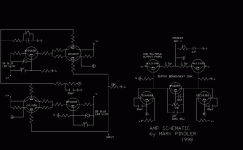
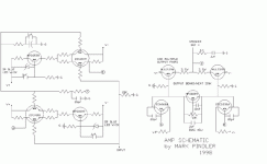
Here is a copy of the basic amp design I threw together and use with fantastic results. I have left out the part values so the DIYer can use it to learn a little too. If done right it is stable into almost any load and is one of the best sounding amps I have ever heard(or not heard! ) You can use voltages up to about 55-60v with no problem as long as you have enough output transistors for the load you are going into. Play with it and see what you get. I'm sure you'll be pleasantly suprised with it. Good luck!
Attachments
markp said:Here is a copy of the basic amp design I threw together and use with fantastic results. I have left out the part values so the DIYer can use it to learn a little too......
How very kind and altruistic.

A lovely and visually symmetrical schematic. Complementry LTPs fed by CCSs to complementry Vas(s) with a amplified diode Vbe betwixt and between to emmitter folowers.
So how do you adjust output offset? Are the non-inverting complementry LTPs base currents so well matched that you don't need a input cap? No drivers that I can see, so how many of those "multiple ouput pairs" can you drive as is? (I can't discern the ouput trans, are they Darlingtons?)
Because, I can read my copy.Bill Fitzpatrick said:Why didn't you put a readable copy up in the first place?
I'm not trying to be God here, I just thought some people would like a place to start learning something about diyaudio rather than just building without doing any calculation or experimentation. If this is not you then bug off, if it is then enjoy your learning. There are things that are meant to be figured out rather than just shoved at you.
It is from AutoCAD which does not import directly into anything friendly to posting.Richard C said:Why is the schematic drawn in such a bizzare way?
Gee, lets see... How about better sounding than any commercial product that is within 10 times the cost. I'd think that is fantastic. This amp can be that good if done right.sam9 said:What is a fantastic result?
markp said:
There are things that are meant to be figured out rather than just shoved at you.
Is one of your teaching goales to show a very odd way to draw a schematic
At least in my opinion one should be able to do without splitting such a simple circuit in half....
Ergo
If you cant figure out how it goes together then you should not be allowed to play with electricty.ergo said:
Is one of your teaching goales to show a very odd way to draw a schematic?
At least in my opinion one should be able to do without splitting such a simple circuit in half....
Ergo

Ooh I do know how to put it together all right. 
It's just that if you want that someone can use it as a learning experiance then it is made too complicated for a beginner DIY person. One would most likely drop the analysis because you first have to figure out how the schematics is built up before you can do any analysis on it... in my opinion it's a wrong way to teach amp design.
Actually I would put the VA stage caps in parallel with collector loading resistors not between base-collector. Many say this improves a sound alot.
Ergo
If you can't put A to A and B to B then you are right they should not try this project. The Miller caps work fine where they are but if you wish to move them that is what this is all about. Having a place to start and doing it from there your way.ergo said:Ooh I do know how to put it together all right.
It's just that if you want that someone can use it as a learning experiance then it is made too complicated for a beginner DIY person. One would most likely drop the analysis because you first have to figure out how the schematics is built up before you can do any analysis on it... in my opinion it's a wrong way to teach amp design.
Actually I would put the VA stage caps in parallel with collector loading resistors not between base-collector. Many say this improves a sound alot.
Ergo
Try to place your post in the threat Single or dual differential?.
It is an ordinary amp with two differential input stages. One thing is unusual - the way of transistor drawing. At the first glance at the schematic in black I suppose that you should place your post in TUBES section.
It is an ordinary amp with two differential input stages. One thing is unusual - the way of transistor drawing. At the first glance at the schematic in black I suppose that you should place your post in TUBES section.
Re: Exporting Autocad Schematics
Or you can export it a bmp then convert it to a gif, as I did. And it was done in minutes.EUVL said:You can export AutoCad files as *.wmf, then put the wmf in a power point sheet, and export the power point as jpg or bmp. Not a direct conversion, but can be done in minutes.
Patrick
- Status
- This old topic is closed. If you want to reopen this topic, contact a moderator using the "Report Post" button.
- Home
- Amplifiers
- Solid State
- My amp design schematic


