This simple circuit can be very good to comparisons with new designs.
The one that teach me that idea was my Sargeant in Army, 1970, his name was Ottmar Albert Furrer from Switzeland.
This man told me, if you can do one amplifier with one single transistor, class A circuit, with one condenser or no condenser, with one resistor, you will make the best!, because each component create one problem... many components many problems.
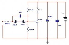
This way i made this in 1971, and never heard nothing better till i heard some class A designs that turns me confused... but, always i prefer this one, because no speaker, you connect to headphones, the best you can find, put in series one or two headphones do divide power and go into 32 ohms or something alike...maximum power is 1 watt, current is 300 miliamperes and supply have to be very well filtered 20 Vdc. 1 Watt can burn some headphones, so best to study headphone first and think about!
dividing by two phones, each one 16 ohms connected in series both sides you will have 3 volts audio each one, and 300 miliamperes flowing througth each phone capsule will hold 500 mw... if you put 4 capsule in series, 2 headphones, one for you and other for a friend, you will have, naturally, 250 mW each capsule.... i think they can hold this power without problem.
Input voltage can reach around 850 milivolts, and be really charged by base to emitter resistor that will reduce output voltage from your source... you can put some control, and also resistance in series to avoid charge problems.
Maximum power is around 1.1 Watts RMS in 32 ohms, and good use 1 square inch heatsink...batteries will go out, the 22 volts will finish in minutes...use a supply, and reduce voltage with transistor, resistor an zener, or use correct voltage and big condenser filtering.
Adjust the value of base to emitter resistance, if you prefer, but is more difficult, adjust resistor form positive to base.... try to measure around half voltage in colector, something around 10 volts DC related to ground, check VBE voltage, if too big (more than 680 Milivolts, reduce it changing adjustable resistor from base to emiter and colector voltage will change a little.... will be good too, because 1 watt is too much, and if you reduce colector voltage, power without clipping will reduce too.
I think this is a reference.... response is wide... can go from 10 hertz flat to 300 Kilohertz easy without loose or distort nothing.
If sounds good is normal, sounding more or less good, take a look in headphone, it may be real Baaaaaad!, check it in another amplifier.
I use it to comparison, use a senheiser Headphone, manufatured in 1970, white color and plastic case, and no speaker, use a microfone capsule, my circuit uses others values because of this impedance.
The advantage, i think, is class A, second advantage, easy to move voice coil, no ressonance because no enclosure, no problems with moving mass because ligth weigth and no ressonances in house, also no reflections.
Good luck
Carlos
The one that teach me that idea was my Sargeant in Army, 1970, his name was Ottmar Albert Furrer from Switzeland.
This man told me, if you can do one amplifier with one single transistor, class A circuit, with one condenser or no condenser, with one resistor, you will make the best!, because each component create one problem... many components many problems.
This way i made this in 1971, and never heard nothing better till i heard some class A designs that turns me confused... but, always i prefer this one, because no speaker, you connect to headphones, the best you can find, put in series one or two headphones do divide power and go into 32 ohms or something alike...maximum power is 1 watt, current is 300 miliamperes and supply have to be very well filtered 20 Vdc. 1 Watt can burn some headphones, so best to study headphone first and think about!
dividing by two phones, each one 16 ohms connected in series both sides you will have 3 volts audio each one, and 300 miliamperes flowing througth each phone capsule will hold 500 mw... if you put 4 capsule in series, 2 headphones, one for you and other for a friend, you will have, naturally, 250 mW each capsule.... i think they can hold this power without problem.
Input voltage can reach around 850 milivolts, and be really charged by base to emitter resistor that will reduce output voltage from your source... you can put some control, and also resistance in series to avoid charge problems.
Maximum power is around 1.1 Watts RMS in 32 ohms, and good use 1 square inch heatsink...batteries will go out, the 22 volts will finish in minutes...use a supply, and reduce voltage with transistor, resistor an zener, or use correct voltage and big condenser filtering.
Adjust the value of base to emitter resistance, if you prefer, but is more difficult, adjust resistor form positive to base.... try to measure around half voltage in colector, something around 10 volts DC related to ground, check VBE voltage, if too big (more than 680 Milivolts, reduce it changing adjustable resistor from base to emiter and colector voltage will change a little.... will be good too, because 1 watt is too much, and if you reduce colector voltage, power without clipping will reduce too.
I think this is a reference.... response is wide... can go from 10 hertz flat to 300 Kilohertz easy without loose or distort nothing.
If sounds good is normal, sounding more or less good, take a look in headphone, it may be real Baaaaaad!, check it in another amplifier.
I use it to comparison, use a senheiser Headphone, manufatured in 1970, white color and plastic case, and no speaker, use a microfone capsule, my circuit uses others values because of this impedance.
The advantage, i think, is class A, second advantage, easy to move voice coil, no ressonance because no enclosure, no problems with moving mass because ligth weigth and no ressonances in house, also no reflections.
Good luck
Carlos
Attachments
Too big iddle current for common headphones
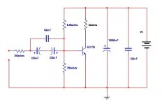
Use this other circuit because too much iddle current, DC iddle current to high... this way, better this one.
Iddle current is 150 miliamperes, voltage colector is 4.5 volts, so you have 640 miliwatts iddle current to divide to small headphones, 4 capsules, each one will hold around 170 mA and audio also reduced. this way more safe.
Good Luck.... sorry the mistake.
Carlos
Attachments
This will fry your mind:
(this is one of those pages that won't allow everyone to link directly to, so use the index and click through)
http://home.kimo.com.tw/skychutw/
CIRCUITS,
HADLEY 622
This is two amplifiers bridged together. Q2 is the sole voltage amplifier for the left half of the amplifier. You could build just half of the amplifier (with 1/4 th the output) if you wanted.
Notice the inverting 'X' type feedback loop.
http://patft.uspto.gov/netacgi/nph-...,376,899.WKU.&OS=PN/5,376,899&RS=PN/5,376,899
click on 'images' and then see Fig.9
You will need a TIFF viewer (free), see FAQs.
Yes, i already perceive my mistake and open an other thread to make less dangerous.
Can have a cooked head, a human barbecue...no good!
awfull taste i believe, and hair between your teeth (aaaaagh!)
And the smell is alike burned horn (do you imagine what means a horn into a man's head here in brazil?.... baaaaad!, very bad!)
regards,
Carlos
Can have a cooked head, a human barbecue...no good!
awfull taste i believe, and hair between your teeth (aaaaagh!)
And the smell is alike burned horn (do you imagine what means a horn into a man's head here in brazil?.... baaaaad!, very bad!)
regards,
Carlos
- Status
- This old topic is closed. If you want to reopen this topic, contact a moderator using the "Report Post" button.