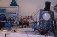
I finally got around to testing my Leach amp. It seems to work, as in that it didn't blow up or oscillate (at least that I could see on my sub-cheapo scope). It clips about 2/3 of the signal off at 1.15V input and stops clipping at about 0.4V input.  I cannot get the output voltage above about 20V. This is with a 40W bulb in series with my power transformer. If I run it normally (no current limiting), it acts similarly, but not clipping quite as early, still really bad though. I am using a test CD and a small CD player as a freq. generator. It cannot go above about 0.4V @1kHz, 1.125V @60Hz.
I have yet to set the bias current.
What do you suppose the problem might be?
I cannot get the output voltage above about 20V. This is with a 40W bulb in series with my power transformer. If I run it normally (no current limiting), it acts similarly, but not clipping quite as early, still really bad though. I am using a test CD and a small CD player as a freq. generator. It cannot go above about 0.4V @1kHz, 1.125V @60Hz.I have yet to set the bias current.
What do you suppose the problem might be?
A 40W globe will probably drop the voltage far to much to allow for correct operation. A 10ohm power resistor usual does the trick for testing or a far higher rated globe.
Sorry but i cant help you regards why the amp is clipping early when directly mains powered. I can only suggest the usual:- check device placement / values, check transistors and diodes for correct function and so on. Is the power supply outputing the correct voltage?
Sorry but i cant help you regards why the amp is clipping early when directly mains powered. I can only suggest the usual:- check device placement / values, check transistors and diodes for correct function and so on. Is the power supply outputing the correct voltage?
Banned
Joined 2002
Kilowatt: I don't know if this would mean anything in regards to using your portable CD player as a testing source. Long time ago while looking at the spec of the CD owner manual, I noticed that regular home CD player puts out 2V while portable CD player only puts out 1V. For listening, I actually have to turn up the volume control more if a Portable CD player is hook up to the pre-amp with everything else staying the same.
Hi,
You don't really have to go the whole mile to build a pre-amp. Just build an attenuator, as mentioned in the thread "Passive Preamp" and hook your regular CD-player to it.
I'm running my Leach Amp using a Pioneer DVD-player + an attenuator. Works like a charm.
You should also try and run it with a 100 ohm resistor instead of your lightbulb...
Good luck,
//magnus
swede said:Hi,
You don't really have to go the whole mile to build a pre-amp. Just build an attenuator, as mentioned in the thread "Passive Preamp" and hook your regular CD-player to it.
I'm running my Leach Amp using a Pioneer DVD-player + an attenuator. Works like a charm.
You should also try and run it with a 100 ohm resistor instead of your lightbulb...
Good luck,
//magnus
Swede,
While the above solution MAY surfice for normal use, a Discman is a poor source for testing purposes and as suggested above should at very least be fed via an active preamp or preferably totally excluded from the test bed.
Also, I agree that a suitably rated 100ohm resistor should do the job well in most cases.
Kilowatt,
If you really want to use a light bulb, use ~ 120V 150W kind.
Sorry if I'm confusing you all...
I did not recommend to use a discman, though the translation from my head to english to the keyboard and over the cyberspace might have indicated so.
What I meant was to use a regular, off the shelf CD-player (not portable).
If you follow Prof. Leach's recommendations on how to test your board, you'll probably find the source of your clipping.
http://users.ece.gatech.edu/~mleach/lowtim/part2.html
As I said before, use two standard 1/4 watt 100 ohm resistors (one for each powerline). Most diy:ers have them laying around in big piles. You are probably not an exception. ;=) That'll do the trick. I've blown a whole bunch of transistors in my earlier tries to get my Leach Amp to work, before I started using resistors instead of fuses when I tested my amps.
And! I think that if the amp doesn't blow up when you have the resistors hooked up, you can go ahead and disconnect them. The amp will behave strange if you still have them there. Try and disconnect your lamp! It might work.
//magnus
//magnus
My first testing was done with Sony Discman(0.7Vmax!).Now i own Marantz CD player.Problem with discman is his weak and low quality signal,so amp cant play loud.Discman in my case added some noise to signal.
100Ohm resistors works fine for me and shoud do same for you.
P.S.I have my share of problems with transformers.At least output transistors are still first
100Ohm resistors works fine for me and shoud do same for you.
P.S.I have my share of problems with transformers.At least output transistors are still first
Hi again,
After some thinking, I believe that you should remove the lamp, adjust your bias and then check for clipping.
The lamp/resistor thingie is only a precaution so you're not blowing stuff up if you connected anything wrong. Since your house didn't burn down, you're probably fine.
//magnus
After some thinking, I believe that you should remove the lamp, adjust your bias and then check for clipping.
The lamp/resistor thingie is only a precaution so you're not blowing stuff up if you connected anything wrong. Since your house didn't burn down, you're probably fine.
//magnus
I did remove the lamp, as is stated (maybe not too clearly) in my first post. It still cipped so that I could not get more than about 22V RMS out. I didn't find anything like that on Prof. Leach's page. Maybe the discman doesn't have enough current capabilty, or maybe there's something minorly wrong in the amp. I'll check it carefully. When I test it with an active preamp, hopefully all will be good. Once I get it in the chassis, I'll just take it up to my regular CD player, hook up some speakers and listen for clipping as I raise the volume. I should finish one more channel (won't take long) before I install them in the chassis because 2 channels go on each heatsink (water-cooled block).
Thanks.
Thanks.
****!!!!!
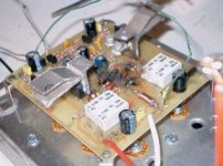
I fried my damn Leach amp board!! It wouldn't look much better if I had put it in the microwave!! While others have their Leach amps running and reproducing beautiful sounds, mine is black and useless. I was trying to figure out why it was clipping, measuring different stages with my scope (from the top of the board ). I must have accidently shorted something out with my oscilloscope probe, which is just a piece of coaxial cable. Good old school tube scope survived, but the center of my amp board sparked an hissed and caught on fire. It looked like if you light a whole book of matches at once. The whole VA and driver stage is gone for sure, looks like someone took a torch to it. The foil pattern might be ruined too, I'm not sure, but my basement smells like burnt resistors, 8 of them burned.
I guess I'll just srap the damn board and make new ones. I'd be lucky to get one good part off it. I really have no idea just how much that board cost me to build, but enough, that's for sure.
Wish me better luck with my next attempt.
I fried my damn Leach amp board!! It wouldn't look much better if I had put it in the microwave!! While others have their Leach amps running and reproducing beautiful sounds, mine is black and useless. I was trying to figure out why it was clipping, measuring different stages with my scope (from the top of the board ). I must have accidently shorted something out with my oscilloscope probe, which is just a piece of coaxial cable. Good old school tube scope survived, but the center of my amp board sparked an hissed and caught on fire. It looked like if you light a whole book of matches at once. The whole VA and driver stage is gone for sure, looks like someone took a torch to it. The foil pattern might be ruined too, I'm not sure, but my basement smells like burnt resistors, 8 of them burned. I guess I'll just srap the damn board and make new ones. I'd be lucky to get one good part off it. I really have no idea just how much that board cost me to build, but enough, that's for sure. Wish me better luck with my next attempt.
Yep, that's why one uses fuses. I've blown a few and
blown a few transistors too, but I've never burned a board.
Cut out the burned components and see if the traces
are intact; bridge them if not with wire unless the board is
too far gone. Retest all your semiconductors from the
VA up; I'd figure that the predrivers are probably blown. I've
seen boards in worse condition still work after the blown
parts were replaced.
You probably had a problem with the driver board to begin
with, but a slipped probe can be instant bad news too.
That's why one uses fuses, right?
Keep trying.
God but you're doing this the hard way; that 'scope is SO
primitive. Do you ever get out Seattle way?
You've got my sympathy. I was checking the bias in an amp once upon a time and the tip of my probe slipped. Smoked a bunch of parts and part of the board. That's a bad feeling.
Don't trash the board unless you're sure it's gone. For one thing, a lot of that black stuff will just be soot. A toothbrush and some ordinary dish soap will clean a lot--maybe all--of that off. If necessary, a quick wipe with lacquer thinner will get rid of some more.
Like Damon said, smaller damage to traces can be bridged quite sucessfully with wire.
Courage, lad, courage...you'll get there.
And the nifty part is that you're going to learn a <i>whole</i> lot more about electronics than some of these other folks do, because this is going to haunt you until you figure out why the circuit didn't work. Once you get that figured out, you'll be in possession of something hard-won--experience--and there just ain't no substitute for that.
Not to mention you've just earned your first war story. Now you can sit back and say,"Yup, and then there was the time back in the summer of '02 when I wasted my amp..." and all the little Neophytes will come crowding around to listen and feel the vicarious chill of knowing Ya Just Did A Bad Thing. Watching them shiver in their boots seems like small compensation now, but it'll be fun then, after the shock wears off.
Grey
Of course it looks reversed, it's a mirror image board (should have paid more attention when I exposed the board). I had to be especially careful when installing the TO-5s for obvious reasons. I was also unable to lay down the drivers as you may have noticed. Believe me, the board layout worked, but there as a problem somewhere or other. I want to use a normal board anyway, so I'll just make a new one, It's not a big deal. I can probably save some parts from the fried board.
Yep, I should have used fuses to test, just as I would have in the finished amp. My whole test setup is just alligator clipped and twisted together. After something like this, one tends to use fuses from then on.
I used MJE15030/31.
P.S. Yeah, my scope is primitive, a PACO S-50. I bought it for $15US. It's not very consistant (one of these days, I'll replace some of those foscilized electrolytics and/or tubes). It has no scale and so must be used in conjunction with an AC voltmeter. It does at least have x1, x10, and x100 attenuation. It has a small bandwidth too. I should sometime buy a nice scope, but I haven't got around to it yet (and they can be very expensive). Hopefully I can find a nice used one for under $400.
Maybe a mirror board will come in handy some time if I can fix it.
You Let The Smoke Out !
Kilowatt,
"Better to have tried and failed, than to have never tried at all"
Anyway, now you know why I ALWAYS use a lamp in series with the AC power feed when running up a repaired amplifier.
I use a 60 or 100w lamp and a variac during initial power up.
A lamp is a positive resistance device, and will provide protection, and a series resistor will not.
A variac is a mandatory investment if you are to do much prototyping.
With the output lightly loaded (100 ohms) a series lamp will allow testing up to clipping without causing the lamp to limit your supply voltages.
Once you have correct output into 100 ohms, you can increase the loading in stages, until you are loading with 8 or 4 ohms, and confirm correct operations at each load impedence.
A sinewave disc on a walkman type CDP should work fine enough for rough testing, and they have variable output at the headphone socket.
Art stores sell thin copper foil, and this can be cut with a scalpel or scissors.
The component lads cutoffs can be vertically soldered to the pcb to provide convenient test points when testing.
An alligator clip lead will connect the test points and your cro lead for testing and measuring.
Better luck next time,
Eric.
- Status
- This old topic is closed. If you want to reopen this topic, contact a moderator using the "Report Post" button.
- Home
- Amplifiers
- Solid State
- I finally fired up my Leach Amp!!!!