Others have commented that ONsemi's models are inaccurate.
Might be best to try and find better models.
have a look at this thread for ideas/info.
http://www.diyaudio.com/forums/showthread.php?postid=1256867#post1256867
Might be best to try and find better models.
have a look at this thread for ideas/info.
http://www.diyaudio.com/forums/showthread.php?postid=1256867#post1256867
here is link to on-semi models for
MJL4281A and MJL4302A
http://www.onsemi.com/PowerSolutions/supportDoc.do?type=models&rpn=MJL4281A
http://www.onsemi.com/PowerSolutions/supportDoc.do?type=models&rpn=MJL4302A
MJL4281A and MJL4302A
http://www.onsemi.com/PowerSolutions/supportDoc.do?type=models&rpn=MJL4281A
http://www.onsemi.com/PowerSolutions/supportDoc.do?type=models&rpn=MJL4302A
AndrewT said:Others have commented that ONsemi's models are inaccurate.
And others have said On-Semi models are pretty good
")
And if I owned a such big company, I would not tolerate to have bad models online
if there were people complaining .. anywhere at www
A few more bad models, my friend, and you are FIRED from working at On.Semi
I have already complained to ONsemi (about datasheet errors) and their reply said they were currently looking at eliminating the contradictions in their Power Semi datasheets.lineup said:
And others have said On-Semi models are pretty good
And if I owned a such big company, I would not tolerate to have bad modles online
if there were people complaining .. anywhere at www.
Mambo said:I noticed a great difference in the BF value of their models, with one = 191 and the other = 505.
From the datasheet they should be very similar;It seems another OnSemi error
My question is, as I do not know what BF is:
Can BF be as different as 191 to 505 for two NPN, PNP in the same class?
MJL4281A NPN has BF=191
MJL4302A PNP has BF=505
Both models were done August 2003
For an ideal BJT whose beta does not vary with current, BF is the same as beta. When beta varies with current, things get a bit messier. See Figure 9 on this page. That shows a plot of ln(Ib) and ln(Ic) vs. Vbe. Decreasing beta at low collector currents comes from the Ib characteristic deviating from the ideal exponential at low currents. Decreasing beta at high currents comes from the Ic characteristic deviating from the ideal exponential at high currents. If the high current and low current regions do not overlap at all, then beta will be constant at mid-current values and BF will correspond to the value of beta in this region. However, for a lot of devices there is quite a bit of overlap between the region where Ib is non-ideal (low currents) and where Ic is non-ideal (high currents). For such a device, BF can be much larger than the actual maximum value of beta.
The actual formulas that SPICE uses for all this are shown starting with equation (1) in the link above.
The actual formulas that SPICE uses for all this are shown starting with equation (1) in the link above.
andy_c said:and BF will correspond to the value of beta in this region. However, for a lot of devices there is quite a bit of overlap between the region where Ib is non-ideal (low currents) and where Ic is non-ideal (high currents). For such a device, BF can be much larger than the actual maximum value of beta.
For a device with a beta spike in the mid-current region like alot of the old TO-66 case power devices, one would expect this. But for a sustained-beta device one would expect the BF to come out at least in the ball park of the flat part of the beta curve. Model extraction algorithms can give stupid non-physical values to parameters if left unconstrained - and that's just operator error. Such models may be "what comes out of the optimizer", but in my particular experience with microwave nonlinear models they typically aren't as robust.
Yeah, the problem is that the datasheets don't usually have the needed plots of Ib and Ic vs. Vbe using a log current scale. If those were available, one could find the regions where ln(Ic) and ln(Ib) fit the ideal behavior. By extrapolating each of these lines, BF could be found by noting that the vertical displacement between the two is ln(BF). Without those, it becomes a guessing game. For the MJL1302A, one would certainly expect BF to match the value of beta in the region where it's constant. But for the MJL3281A, beta increases with increasing current up to pretty large Ic. One needs to have telepathic powers to really know what's happening here without the needed data.
Thanks, andy_c, for explaining.
Now I get the big picture of BF (ideal maximum forwartd beta)
As I am not very interested in the abstract functions
I just downloaded http://andycpublic.50webs.com/downloads/mjl_3281a_1302a.mod
You have done an excellent work & article. 4 pages with figures!
Improved SPICE Models for MJL3281A and MJL1302A Power Transistors.
http://andycpublic.50webs.com/spice_models_1.htm
Thanks again.
I get it, I can trust your models, fairly. At least they should not be better than most spice models out there.
And MJL4281/MJL4302 vs. MJL3281A/MJL1302A should not be too different.
I did a run of on-semi spice of MJL4281+MJL4302.
VBE vs. Current looks very good.
But HFE base current vs. collector current is very bad.
The PNP MJL4302 has way too high gain. (Should be lower than the NPN)
When I changed to BF=191 (from 505) and so using same BF for both PNP and NPN the curve matched much better.
Judging from the datasheet the BF for the PNP should be a bit lower.
But how much lower I do not not know.
I will do same run using your models for MJL3281A/MJL1320A.
Your data shows very much higher BF for the NPN
and not the other way
On-Semimjl3281a_x npn IS=9.8145e-12 BF=438.0
mjl1302a_x pnp IS=9.8145e-12 BF=122.925
mjl4281a npn IS=9.94641e-11 BF=191.836
mjl4302a pnp IS=8.52181e-11 BF=505.26
PS. Andy_C
There are one link you should update, as it has been changed
by www.vacuumstate.com
Secrets of the Phono Stage ... Allen Wright
http://www.vacuumstate.com/fileupload/SP_15_Article.pdf
There are one link you should update, as it has been changed
by www.vacuumstate.com
Secrets of the Phono Stage ... Allen Wright
http://www.vacuumstate.com/fileupload/SP_15_Article.pdf
Andy_C,
Let me first say that I do not know what these actual numbers represent. If we take into consideration that the items you used for the simulations are current production units and not extracted from the original beta testing batch could this not be part of the problem.
I construct amplifiers from the designs which are provided to use by the more skilled individuals on this forum. I buy my devices from supposed reputable companies. If the current parts for sale are being manufactured overseas to substandard specifications where does that leave us as the consumer.
I applaud all of your work and think more should be done to assure us, as consumers, that we are paying for the quility we expect to find. On Semiconductor, formerly Motorola, was always considered to be a vanguard of quality. Are we to suspect there entire line is defect??? Sanken and Toshiba are alternatives, but difficult to source in some areas and wholly more expensive.
Have you performed any tests to verify the earlier models manufactured by On Semi are close to stated performance.
My two cents and thanks Tad
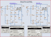
Here is my test to see how Andy C models simulate, compared to current models for download at OnSemi
http://www.onsemi.com/PowerSolutions/supportDoc.do?type=models
This setup uses 2 complementary parallelled pairs for Push-Pull output.
Class A biased at 1.77A (0.88 A per transistor). Supply is +-20 Volt.
Test level is 8 Watt into 8 Ohm.
Andy C models gives a bit higher -3 dB frequency, too: 27 MHz vs. 21 MHz
THD 0.007 % without feedback.
The 3rd is higher than the 2nd harmoincs, in this output stage
Do I have to tell, what spice models I will use, from now on
Attachments
lineup said:Thanks again.
I get it, I can trust your models, fairly. At least they should not be better than most spice models out there.
Hi lineup,
It would be a mistake to trust my models too much I think. wg_ski brought up a great point above about using optimization to find transistor parameters, and the possibility that this could lead to non-physical solutions. This is a real problem that's often unavoidable because the datasheets don't have all the data needed to fit the parameter values. That's because the required data for SPICE modeling usually isn't important to the end user of the device.
Compare this to what a guy like Scott Wurcer has available. I'm sure the AD people have all the resources they need and more to measure everything necessary to get extremely accurate models. Not to mention an intimate knowledge of the semiconductor process itself. Scott has mentioned in the past that he's able to get simulation results "so close it's scary" or something to that effect. But the average person trying to do the same thing with only the data available from a discrete device datasheet can never get there.
Thanks for the note about the broken link to Allen Wright's page. I'll fix that.
tryonziess said:Andy_C,
Let me first say that I do not know what these actual numbers represent. If we take into consideration that the items you used for the simulations are current production units and not extracted from the original beta testing batch could this not be part of the problem.
Hi Tad,
All I did was try to get SPICE parameters such that the simulated performance of things like beta vs. Ic, fT vs. Ic. capacitance vs. reverse voltage etc. match the datasheet curves as closely as possible. As part of that, I have to assume that the data measured by the manufacturer is correct. I don't have any of the equipment required to verify the manufacturer's measurements of the device.
In other words, the problem with the models provided by the manufacturer is that their simulated data doesn't even match the datasheet. There is no problem with the devices that I know of.
I made these models back in October of 2006. At that time, I met Bob Cordell at the Rocky Mountain Audio Fest and had some discussions with him. He convinced me to look at using FETs for output devices. That's what I ended up doing, so I haven't had a chance to compare the simulated results using the OnSemi BJTs to the actual measured performance of an amplifier.
andy_c said:I'm sure the AD people have all the resources they need and more to measure everything necessary to get extremely accurate models. Not to mention an intimate knowledge of the semiconductor process itself. Scott has mentioned in the past that he's able to get simulation results "so close it's scary" or something to that effect.
And I'm sure they'll provide you "scary accurate models". For a fee. A steep one.
- Status
- This old topic is closed. If you want to reopen this topic, contact a moderator using the "Report Post" button.
- Home
- Amplifiers
- Solid State
- MJL4302 & MJL4281 Models