Hi!
Hi want to make a power supply using the Lm317Hv, but I want that the Vout goes from 0 to 50v aprox. How can I make to reduce the vout from 1.25 to 0V?. Seeing the datasheet I see that I can use a zener diode but then I need a negative supply.
What can I make?
It´s posibble to go over the 1.8A?

Hi want to make a power supply using the Lm317Hv, but I want that the Vout goes from 0 to 50v aprox. How can I make to reduce the vout from 1.25 to 0V?. Seeing the datasheet I see that I can use a zener diode but then I need a negative supply.
What can I make?
It´s posibble to go over the 1.8A?
Floating regulators can withstand only a limited input-output voltage difference and for LM317 this maximum voltage is 37V. Also, the maximum instantaneous current the regulator can supply depends on the input-output voltage diference [due to pass-element SOA and power dissipation limitations] as can be seen in the datasheet, ie : 2A for 5 to 12V, 1.7A at 15V, 1.4A at 20V, 1A at 25V, 0.6A at 30V, 0.4A at 37V [maximum allowed dissipation is 25W, look at the datasheet for further details]
In my experience, when one of these LM-series floating regulators sees more than 40V input-output difference it does not usually blow but it shuts down and latches in an off state until input voltage is supressed [ie: power down the circuit and discharge input filter capacitors], then it starts working again. I have a couple of LM338 [5A version of LM317] with 58V in [max.] and providing 40V out in a dual regulated power supply that have shut down several times due to output overcurrent conditions and still survive [I blew only one unit in about 7 years]
So to achieve such a variable power supply in a reliable way with a LM317 or similar floating regulator you will have to design a pass circuit [connected in series with the regulator input] with the purpose of keeping the input-output voltage difference seen by te regulator at 7..10V or so. This will allow for 2A output currents at 50V or higher output voltages and that circuit may be as simple as a power darlington [ie: TIP142 or similar] as a pass element, a resistor and a zener but I haven't tried it yet
In the other hand, getting outputs lower than 1.25V would require a regulated negative supply, but I see no purpose on such low output voltages
Finally, to reduce power dissipation you may opt to use multiple supply rails depending on the output voltage selected [ie : 20V for 0..10V, 40V for 10V..30V, 60V for 30V..50V, etc...], you may even add automatic supply rail switching functions using comparators, diodes and fets or power darlingtons, but this markedly increases circuit complexity
Faith for untested things?
Hi Pablo!
...looks like the LM317 is not perfectly suited for your demands.
Circuitry increases more and more....
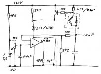
May be a solution similar to the attached schematic would serve
your purpose better.
Component count seems reasonable for me.
Please note, that this is not a tested circuit. Just a first idea.
So it might require some struggles to get it running in real life.
...hope I did not put some major flaws to this design...
The OP amp must allow input voltages that touch the negative rail.
I.e. LM358. If you use this please do not forget to tie both inputs of
the second integrated OP amp towards ground.
If you chose a different type you should take care about its idle current and you might have to adjust the 220 Ohms which are
connected to the positive rail.
I would let the OP amps output work into a resistor towards ground
and use the supply current of the OP amp to drive the power darlington. TIP147 would be at the limit, but you could parallel two Tip147 and give 0.68 Ohms to each emitter instead of a single
darlington with 0.33 Ohms.
The current limiting transistor can be any small signal BJT, i.e. BC560.
The Z39 reduces the supply voltage to an acceptable value for the
OP amp. LM 358 will see a lot of ripple in its supply voltage, but should be able to deal with this.
Oscilation is always a matter of concern, but if you use a big cap at the output (i.e. 1000uF), then I would not expect oscilation.
Some further proposals to improve:
-You might think about an additional protection diode between "out" and "ground".
- Putting 100k between the OP non inverting input and ground, would avoid high output voltage if the slider of the potentiometer starts flying.
- Instead of a Z5.6 you could use a precision reference.
Still lots of LM358 and TIP147 and BC 560 in my assortments ... ..waiting for suitful purpose. Spain is not that far... could send some.
Bye
Markus
Hi Pablo!
...looks like the LM317 is not perfectly suited for your demands.
Circuitry increases more and more....
May be a solution similar to the attached schematic would serve
your purpose better.
Component count seems reasonable for me.
Please note, that this is not a tested circuit. Just a first idea.
So it might require some struggles to get it running in real life.
...hope I did not put some major flaws to this design...
The OP amp must allow input voltages that touch the negative rail.
I.e. LM358. If you use this please do not forget to tie both inputs of
the second integrated OP amp towards ground.
If you chose a different type you should take care about its idle current and you might have to adjust the 220 Ohms which are
connected to the positive rail.
I would let the OP amps output work into a resistor towards ground
and use the supply current of the OP amp to drive the power darlington. TIP147 would be at the limit, but you could parallel two Tip147 and give 0.68 Ohms to each emitter instead of a single
darlington with 0.33 Ohms.
The current limiting transistor can be any small signal BJT, i.e. BC560.
The Z39 reduces the supply voltage to an acceptable value for the
OP amp. LM 358 will see a lot of ripple in its supply voltage, but should be able to deal with this.
Oscilation is always a matter of concern, but if you use a big cap at the output (i.e. 1000uF), then I would not expect oscilation.
Some further proposals to improve:
-You might think about an additional protection diode between "out" and "ground".
- Putting 100k between the OP non inverting input and ground, would avoid high output voltage if the slider of the potentiometer starts flying.
- Instead of a Z5.6 you could use a precision reference.
Still lots of LM358 and TIP147 and BC 560 in my assortments ... ..waiting for suitful purpose. Spain is not that far... could send some.
Bye
Markus
Attachments
output overshoot
...some more thoughts:
From theory I would expect some overshoot at the output
during turn on. This would be caused, because the 10uF cap
of the OP supply will draw some current during turn on.
This current will give a voltage drop across the 220 Ohms at the positive rail and this give it signal to the power darlington.
In general this may also cause issues if the 60V rail is heavily modulated.
Quantity of this effect will depend not only on the LM358, but
very much on the current gain of the darlington and the ratio of
the output cap / OP-cap.
If the current gain would be very high then the ration of
transfered charge would be determined by 220 Ohms / 0.33 Ohms.
So I would propose to reduce the 10uF across the OP amp as much
as possible. Say 100nF? (Output cap with 1000uF as proposed first should be fine then)
100nF should filter all HF from the OP supply.
For low frequencies the supply voltage of the OP itself will then follow the modualtion of the 60V.
...should be acceptable as long as the 60V rail is running somewhere between 50V-65V.....
OP supply will then move between 11V-26V, which is acceptable if we consider the 100db PSRR....
@All:
Ideas, concerns or even "NO GOs" are welcome from my side.
Cheers
Markus
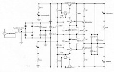
Let me show You my PowerSupply design:
www.hszk.bme.hu/~sp215/elektro/Tap3.gif
I haven't duild it yet, but some othets did, and they said it worked fine. Not so simple, as the previous, but it has much better line regulation, and adjustable current limiting 0 to max, and limiting indication. If You replace the voltage reference to TL431, the load regulation will increse further. The 22k resistor may should be replaced with 15k, especially if the input voltage is lower than 50V.
Bye!

Zero volts cannot, this circuit cannot!
To reduce voltage change the 15 V zener into a 1n4002 diode, but put arrow oposite direction related to zener when assembled. (minimum voltage is this zenner more one transistor saturated VCE and two VBEs) .
The test i make with supplies and amplifiers is, switch on supply, put it on short and go to have a shower....if alive when i return... good!.... if dead....Junk!...never Junk because normally i put heavy material on amplifiers and supplyes... to hold shorted DC power and some more amperes and heatsinks too.
Amplifiers i do the same... i measure supply shorted current... so transistors are put in parallell to hold that...not fuses, fuses is normally 25 ampéres to protect house mains wiring.
Not so crazy, i have maid here... and sometimes put their hands on my table... and a mass there... a small short and boomm!... this way can short, melt wires...make smoke!... and no problem at all, always people in my house to avoid fire.
I am not a little crazy, maybe entirelly crazy.... crazy for my daugther, crazy for friends, crazy to have fun.
MY old supply voltage will start in 2.0 volts or a little bit more than that.
regards,
Carlos
....like your circuit, Carlos.
May be I would add an adjustable current limit.
..don't need to call me a softy...
I am already aware of this

This mentality will help me to survive and avoid
during my motorcycle tour and ongoing off road exercises
next days ... :cool
Cheers
Markus
May be I would add an adjustable current limit.
..don't need to call me a softy...
I am already aware of this
This mentality will help me to survive and avoid
during my motorcycle tour and ongoing off road exercises
next days ...
:coolCheers
Markus
Hi!
Thanks to alls!
Maybe I must explain a little more the purpose of my power supply.
In fact I must do two power supplies, because I want to conect FET transistors to the power supplies, so I need a positive power supply and a negative. The problem is that I need a very low ripple at the output. So I think that I must use comercial regulators. I´m going to use the LM117HV linear regulator, he can go from 1.2 to 57V and 1.5 A. Can I conect two or three of those regulators with the adjustements pins conected? They´ll be controled by one single variable resistor...
- Status
- This old topic is closed. If you want to reopen this topic, contact a moderator using the "Report Post" button.
- Home
- Amplifiers
- Solid State
- problems with my power supply