Hi!
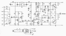
Here is The Ion Obelisk! It is a Class AB 30W amp with astonishing musical sound. The designer was Richard M. Hay ( also designer of some Radfords! ) The Ion is the basic of the legendary Nytech amps.
It is easy and cheap to build and living with it too. (small and little heat).
The amp build with turn on thump blocker and overcurrent protection.
I didn’t say that it is the best amp, but it can easily outperform many comercial amps.
I will continue with part list, more detail and some more photo.
The schematic is a version of the Ion Obelisk.
Greetings for every Diyer!
Attachments
Destroyer X will turn into Constructor one
Good!. thanks Hungary!
Send part list please. I am waiting walking from left to rigth in my apartment... i will make a trail so much i am passing same place to see your parts! (not a joke, ansious, crazy to see it).
I will simulate it as it appear in forum.
Carlos
Good!. thanks Hungary!
Send part list please. I am waiting walking from left to rigth in my apartment... i will make a trail so much i am passing same place to see your parts! (not a joke, ansious, crazy to see it).
I will simulate it as it appear in forum.
Carlos
Tyimo, i want to know some of Pirro
Pirro Victory, a think Thermophiles, Greece...only General Pirro stay alive, whole warrior dead figthing.
We use as a say here, when you win something with too much efforts and with too much sadness.
If you like to inform, please, write some letter directly to my E Mail, this way, we will no scape from the thread amplifier.
nanabrother@yahoo.com
Thanks in advance by your kindness.
Carlos
"Nothing like a NAD 3020, remotely."
Q601 and Q605 of the NAD comprise the voltage gain stages, other than being opposite polarity they are hooked up the same.
The Ion uses an active current source for the VAS, the NAD a bootstrap. Big deal.
Actually , AKSA claims it is a big deal, and that the bootstrap sounds better.
They both use complementary darlington connected output driver pairs. NAD uses discrete transistors.
The Ion has an output cap.
The Ion has foldback current limiting that will make nasty 'farting' sounds if activated driving low impedance loads.
Hello Sreten an whole people in this thread
This problem is very difficult to Judge because i lived some experience alike that.
I decided to return some decades to find an amplifier, the new ones with simetrical, double simetrical thopologies in differential input, with pnp and npn sounds horrible, awfull to me... only good treble, and strange bass.
This way i returned eigthies, then i found one easy to construct Sony, and as i worked for them and i see the way they judge, passing whole day sitting and comparing hearing music, not instruments, with glass cleaner to President sitted together... and when finish they see graphics and instruments.... they know very well the good distortions, the bad ones ,... who is good and who is bad.
The choice was Sony thopology.... this way i put thopology and start to calculate whole amplifier since the beginning.... each resistor, each condenser..... do it again, other transistors and other voltage.... do you know what happened?.... very similar Sony... and i made thopology coppy, not entire amplifier coppy... then i put it to simulate, and latter i put it to work.... good sound.... interesting bass...not so good voice or treble...but interesting non precise bass.... without short bass tone...not a boom!..... it make a boooooooooooommmmmmm!...longest one, i prefered...personal taste.
Then, so happy i was, i made some damn pc board design, an scratch with transparent board and parts on it... easy to make and understand and copy, and construct..... do you know what happens.... exactly, or very close to P3A from Rodd Elliot... and Rodd make their amplifier before Japanese... i contact Sony friends and asked them when they made design.... Rodd was the first related Sony.
And someone asked P3A board.... i tried to send by mail... could not.. and i made the foolish, i put it on forum and some Sweeden man, do not remember the one, told me that this is no good, because Rodd was making PCboards.
I was ashamed because so fool i was... and i asked moderator to erase all thread, and they donne it for me.
In the real world, i do not copy Rodd, i copy Sony Thopology only.... and matched with Rodd P3A as an accident.
This way, this schematic shown, may have absolutely nothing related to NAD schematic.... only damn similarities, that can happens because i lived this sittuation in true life moment!
By the way, can you inform me, in forum or directly to mail adress, How is this NAD sound, have you heard it?.... how this undistorting method works, and what problem this no distortion method can create when not working yet. If you can help me....heellllp!
nanabrother@yahoo.com
Thanks by attention
Carlos
how does a NAD3020 sound ? Interesting question.
I've heard several over the past 25 years or so in different types
of systems from serious "HiFi" to thrown together stuff.
Well first off it goes louder than you would think and it is does
not have any problems with difficult loads. Compared to other
rated amplifiers at the time (I had a supposedly "good" JVC)
it sounded relatively unrestricted and dynamic.
However over the years your discrimination improves, and
the 3020 is not the last word in amplifier design. The internal
wiring is far too messy for it to achieve high resolution.
But a landmark design - and still very listenable to.
There were several single ended input single rail designs in the
The NAD's day like the Nytech / Ion. I can't remember the models
off-hand, they all sounded nice but lacked real power and some
struggled with less than ideal loads.
IMO the Mission Cyrus 1 set the benchmark for serious "HiFi"
budget amplifiers. Good resolution, good imaging, can be
played loud without falling apart, sounds "together".
For the stock amplifier bass is slightly weak.
The Cyrus II and PSX comprehensively sort that out.
") sreten.
sreten.
I've heard several over the past 25 years or so in different types
of systems from serious "HiFi" to thrown together stuff.
Well first off it goes louder than you would think and it is does
not have any problems with difficult loads. Compared to other
rated amplifiers at the time (I had a supposedly "good" JVC)
it sounded relatively unrestricted and dynamic.
However over the years your discrimination improves, and
the 3020 is not the last word in amplifier design. The internal
wiring is far too messy for it to achieve high resolution.
But a landmark design - and still very listenable to.
There were several single ended input single rail designs in the
The NAD's day like the Nytech / Ion. I can't remember the models
off-hand, they all sounded nice but lacked real power and some
struggled with less than ideal loads.
IMO the Mission Cyrus 1 set the benchmark for serious "HiFi"
budget amplifiers. Good resolution, good imaging, can be
played loud without falling apart, sounds "together".
For the stock amplifier bass is slightly weak.
The Cyrus II and PSX comprehensively sort that out.
sreten.the schematic you posted differs sigificantly from orginal service schematic drawing I have for the ION SYSTEMS OBELISK 1 from 1990 by R.Hay
Line Input stage: no
Input switch: fully different
Disc stage: missing
Amp: differences
psu: fully different
Please check your sources / or your drawings
Line Input stage: no
Input switch: fully different
Disc stage: missing
Amp: differences
psu: fully different
Please check your sources / or your drawings
Parts List
Hi!
Here is the parts list! Sorry for the late!
Ion Obelisk Parts List
R1,8 ,23, 29, 32 10 K
R2, 13 12 K
R3, 9, 40 560R
R4 2.2 M
R5 270K
R6 22 K
R7, 24, 38 1.8 K
R10, 11, 39 3.9 K
R12 27 K
R14, 16 39 K
R15 47 K
R17, 20 1.2 K
R18, 19, 33, 34 150R
R21 220R Trimmer
R22, 25 270R
R26 680K
R27, 28, 30, 31 100R
R35, 36 0.33R 2W, 1%
R37 10 R
C1, 3, 14 10uF, 35V, ELKO
C2 100pF, 100V
C4 470pF, 100V
C5, 6, 10, 15 22uF, 63V, ELKO
C7, 8 68pF, 100V
C9 100uF, 35V, ELKO
C11, 12 10nF, 100V
C13 6800uF, 63V, ELKO
C16, 17 10nF, 100V
C18 10000uF, 80V, ELKO
P1 50K, ALPS
D1-5 1N4148
D6-9 1N5402
T1 BC549C
T2 BC559C
T3, 6, 7, 9 BC556C
T4, 8 BC546C
T5 BD139B
T10 BDT65C
T11 BDT64C
TR1 230V/48V/min: 2.5A, Torroid, (120-160VA )
Bias: 30-50mA, adjust R21, measure the voltage drop on R35-36:10-20mV.
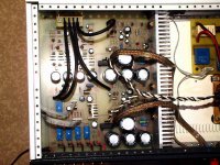
Later comes the pics!
Greets:
Tyimo
Hi!
Here is the parts list! Sorry for the late!
Ion Obelisk Parts List
R1,8 ,23, 29, 32 10 K
R2, 13 12 K
R3, 9, 40 560R
R4 2.2 M
R5 270K
R6 22 K
R7, 24, 38 1.8 K
R10, 11, 39 3.9 K
R12 27 K
R14, 16 39 K
R15 47 K
R17, 20 1.2 K
R18, 19, 33, 34 150R
R21 220R Trimmer
R22, 25 270R
R26 680K
R27, 28, 30, 31 100R
R35, 36 0.33R 2W, 1%
R37 10 R
C1, 3, 14 10uF, 35V, ELKO
C2 100pF, 100V
C4 470pF, 100V
C5, 6, 10, 15 22uF, 63V, ELKO
C7, 8 68pF, 100V
C9 100uF, 35V, ELKO
C11, 12 10nF, 100V
C13 6800uF, 63V, ELKO
C16, 17 10nF, 100V
C18 10000uF, 80V, ELKO
P1 50K, ALPS
D1-5 1N4148
D6-9 1N5402
T1 BC549C
T2 BC559C
T3, 6, 7, 9 BC556C
T4, 8 BC546C
T5 BD139B
T10 BDT65C
T11 BDT64C
TR1 230V/48V/min: 2.5A, Torroid, (120-160VA )
Bias: 30-50mA, adjust R21, measure the voltage drop on R35-36:10-20mV.
Later comes the pics!
Greets:
Tyimo
Hello tyimo from hungary

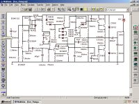
I already simulate your amplifier, and is not finished yet...voltage in output, middle voltage is not correct (32)
Also have some things to change a little because some small instability in hi frequencies.
But low frequency response was very good... new designs do not reproduce (in simulator) square and triangular waves like this amplifier did.
Power is 80 watts rms in 4 ohms...but it will produce more when finished (is not finished), but still working in simulator now!
I use other "TRANZSZISTORZ"...very interesting language!
Those electrolitic coupled amplifiers somethimes surprised me a lot.
Thank you... i was happy to test it in simulator, in the future it will tested real world.
Sorry, but i made some modifications in your PZOLTAN HUNGARY
regards,
Carlos
Attachments
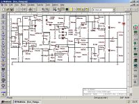
Tyimo, it is working reasonable on simulation
Power was a little more than 100 watts RMS at 4 ohms
- 3 dB points are 10 HZ and 40KHZ
Sinusoidal perfect till 60 Khz, square wave good from 50 Hz to 18Khz
Sensitivity is around 70 milivolts in input to 105 watts output on 4 ohms... an resistor divider in input allow you use 775 milivolts.
Maximum current is 2.3 Amperes DC
Voltage used was 68 Volts, voltage on amplifier center, the output before condenser is 34.5 volts DC.
Bias adjusted in 100 mA.... all transistor VBE voltage good.
Non oscilation, a little modified Eva Method, because could not use 1 uF, audio was cutted in simulator.
Efficiency around 60 percent.... consumption near 160 Watts
Very good square wave on low frequencies around 20 Hertz... difficult to find in new designs.... on simulator Multisim.
Reallity may be different, but will work!
regards,
Carlos
Attachments
 [they are mostly useful in SMPS]
- Status
- This old topic is closed. If you want to reopen this topic, contact a moderator using the "Report Post" button.
- Home
- Amplifiers
- Solid State
- Ion Obelisk