I have been looking into a Kenwood Basic M2 Power Amp, initially to unravel the pinout/operation of its output devices (sanken DAT1081 DAT1521) and found the most interesting thing.... 4 devices/ch... 2 on +-45V and 2 on +-80V more interesting that is the device emitters are all paralell via the emitter resistors - has anyone seen this type of circuitry - and how does it avoid the 35v drop across the devices in high output? i guess a schematic would be useful - i can understand its operation if it were to switch supply or output between the 2 sets of devices (emulating the class H style circuit or for different impedances) nonetheless the irony of its nomeclature (BASIC M2) is not lost upon me - it appears far from basic.
suggestions? ideas? even better experience? plz enlighten
regards Baily
suggestions? ideas? even better experience? plz enlighten
regards Baily
Sreten has got it right.
The M2/ M2a run off dual rails. +/-56 and +/-91vdc. The smaller kenwoods run off +/-46 and +/-76vdc.
The DAT's which are basically 2 trannies in one have a common collector but separate B and E.
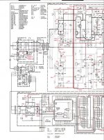
This not a commutation driven circuit but a pretty elaborate switching IC does the work of feeding each set of outputs. The TA2031 you see next to the heatsinks does that job.
Additionally there are big diodes on the collectors of the low rail devices that avoid leakage of higher voltage rails.
The obvious advantage is heat, these things run cool, this is a class-G design using Kenwoods DLD switching.
If you have tried to construct an amp using +/- 91 volt rails, you will know how easily you can get thermal runaway.
In my opinion, this is a very underrated design, it sounds pretty good and has killer bass. Tight and controlled not bloated and overdone. Damping of these units is in excess of 1000.
For the money, they are hard to beat.
K-
The M2/ M2a run off dual rails. +/-56 and +/-91vdc. The smaller kenwoods run off +/-46 and +/-76vdc.
The DAT's which are basically 2 trannies in one have a common collector but separate B and E.
This not a commutation driven circuit but a pretty elaborate switching IC does the work of feeding each set of outputs. The TA2031 you see next to the heatsinks does that job.
Additionally there are big diodes on the collectors of the low rail devices that avoid leakage of higher voltage rails.
The obvious advantage is heat, these things run cool, this is a class-G design using Kenwoods DLD switching.
If you have tried to construct an amp using +/- 91 volt rails, you will know how easily you can get thermal runaway.
In my opinion, this is a very underrated design, it sounds pretty good and has killer bass. Tight and controlled not bloated and overdone. Damping of these units is in excess of 1000.
For the money, they are hard to beat.
K-
Thankyou very much for your input...
sounds like you're spot on... through my meter tests i established them DAT devices were common collector output devices, i was interested why the dual rails, which was explained has anyone got a schematic or info on the theory of operation of an amp this class?????
i accept the fact that this runs cooler, though i am interested in how so especially on constant high output over longer duration (as i believe that using 2 devices over 1 load makes the device run 2x as hot as running 2x device over 1 load) - moreso interested in the switching....... especially as the voltage amp ic drives all this (i gather this ic cleverly switches from LV devs to HV devs transiently based on output voltages thus switching from one set to the other over the voltage = lower heat per device per sine<360 electrical deg>)
i must say i find this circuitry highly interesting (coming from a single rail background)
Regards Baily

QUOTE K-Amps The VA amp is pretty standard. The switching IC comes AFTER the VA and driver stages. I have bypassed the TA2031 and the amp runs fine on any one set of outputs... only that it runs real hot!..................................
i wonder why????????????
sounds like K-amps was right earlier
This not a commutation driven circuit but a pretty elaborate switching IC does the work of feeding each set of outputs. The TA2031 you see next to the heatsinks does that job.
- from my knowledge of output devices this amplifier workd like a four barrel carburettor - the LV rail handles the signal till the level requires the HV rail to switch in for higher signals
but if P=IxV 2 devices will run hotter than 4 though at seperate intervals (possible heat saving) as im inexperienced with such circuitry (but wish to know this fully) i have a Technics SE-A3MK2 - which i will check all collector voltages (i wonder if its dual V)
i must say i enjoy figuring this innovative drive circuit out
Regards Baily
SVI2004A said:QUOTE
- from my knowledge of output devices this amplifier workd like a four barrel carburettor - the LV rail handles the signal till the level requires the HV rail to switch in for higher signals
Regards Baily
No. The lower rail devices will be reverse biased - hence the diodes - and stop conducting - so your analogy is incorrect.
") sreten.
sreten.SVI2004A said:
- from my knowledge of output devices this amplifier workd like a four barrel carburettor - the LV rail handles the signal till the level requires the HV rail to switch in for higher signals
Regards Baily
The nearest to this is the Edwin topology, but no real advantage.
sreten.The LV OP runs till it is close to it's rails then the TA2031 switches the audio signal to the higher HV OP stage.
The switching is such that they never conduct simultaneously.
It is also not that the LV OP's handle a clipped signal and the HV provides the additional "crest" of the sinewave, but that lets just says that given a single cycle of a sinewave, and assume it represents a bell shaped curve, 2 standard deviations are handled by the HV OP and the rest by the LV OP stage.
The obvious advantage is that no set of outputs sees greater than +/-50 vdc or so across their CE's so dissipation is very low.
K-
- Status
- This old topic is closed. If you want to reopen this topic, contact a moderator using the "Report Post" button.
- Home
- Amplifiers
- Solid State
- Kenwood Basic M2 - Intriguing Circuitry