I’m about to wire my first PS. The trannie is 300 VA, with about 34 volts on the rails. I am bussing the PSU caps a side, rather than a star ground.
It was suggested to me that the 0.7 mm (I think that’s 36 gauge) wire I was going to use may not be adequate, and I should use 1.0 mm (25 gauge).
I'd be happy to do use heavier wire, but the only 1.0 mm (locally at Jaycar anyway) is enamelled, which would require a lot of fiddling to remove the enamel at the numerous points on the wire (eg the 4 caps a side).
I could strip the PVC jacket off normal insulated wire, but as my wire is stranded, I believe I’d need to tin the ends of the wire before you
stripping the insulation from it, to stop it falling apart. Also,
I’m told I should tin the entire length of the wire to prevent oxidation – all this is a little time consuming – there must be a quicker way
A long term technician has just told me that he thinks 0.7mm will handle about 5 amps. The *output current limit is typically 11.5 amps. I don’t know the formula for the current within the PS but imagine it would be a lot less than on the output side of the chip (the LM3886). I'm posting in SS because I think you guys know more!")
Do you think 0.7 mm enough, or what would you suggest?
Thanks
Richard
It was suggested to me that the 0.7 mm (I think that’s 36 gauge) wire I was going to use may not be adequate, and I should use 1.0 mm (25 gauge).
I'd be happy to do use heavier wire, but the only 1.0 mm (locally at Jaycar anyway) is enamelled, which would require a lot of fiddling to remove the enamel at the numerous points on the wire (eg the 4 caps a side).
I could strip the PVC jacket off normal insulated wire, but as my wire is stranded, I believe I’d need to tin the ends of the wire before you
stripping the insulation from it, to stop it falling apart. Also,
I’m told I should tin the entire length of the wire to prevent oxidation – all this is a little time consuming – there must be a quicker way
A long term technician has just told me that he thinks 0.7mm will handle about 5 amps. The *output current limit is typically 11.5 amps. I don’t know the formula for the current within the PS but imagine it would be a lot less than on the output side of the chip (the LM3886). I'm posting in SS because I think you guys know more!
Do you think 0.7 mm enough, or what would you suggest?
Thanks
Richard
Oz supplier
FYI:
I found an Australian mail order supplier of 'heavier' tinned wire, and will get some from them
http://www.finnsglass.com.au/home.htm
The largest they have is 16 gauge: 1.3 mm, should be ok.
Someone else had bigger wire, with much larger MOQ.
FYI:
I found an Australian mail order supplier of 'heavier' tinned wire, and will get some from them
http://www.finnsglass.com.au/home.htm
The largest they have is 16 gauge: 1.3 mm, should be ok.
Someone else had bigger wire, with much larger MOQ.
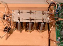
The rule of thumb is very simple here: as thick as you can get to fit. You can use solder wire-mount pieces to the PSU wires from dismantled screw wire-to-pcb connectors to get 2.5mm for this with a soldered connection without having pcb mounting problems. You need an 100W soldering iron/gun to tin and mount bigger wires in the amp.
1 is 'wire-to-pcb screw connectors'
2 is a connection made by soldering a part I got from dismantling 1 to the 2.5mmwire/pcb
It's very ugly, unpractical if you plan to separate the connections in the future but now I don't have to concern about having additional resistance points which vary with the amount of current drawn from the PS in my 'vewy vewy pwecious wails'.
edit: Sorry, english is not my native language, and I messed it up a bit with the 'thingie that you take from there and do that other stuff'
Attachments
Well, an issue that havnt been addressed here is the type of wire.
Looking at Lucpes's example it seems to be worth mentioning.
The insulation material should be of a reasonable quality and thickness. Personally I never use anything but fibreglass or teflon. Regular mains voltage rated wire should be ok, but in case something gets hot glass or teflon will provide an additional safety margin. I like the thought of that. What also should be mentioned for the same reason is that there is a reason why rectifier bridges have spade terminals, and its not to have more surface to solder the wires to, but to be able to use crimped spade termination for the wires attached to it. Again it for the sake of a decent safety margin in case something goes wrong, or in some cases as with big class A amp, simply cause the load requires spade termination.
Magura
Banned
Joined 2002
why do people use speaker wire for hook up wire.. WHy .. no one has ever answered this to me but.. Humm... why not just buy the proper wire or strip apart something with proper wire.. i have tons of it i keep all computer psu's and use that wire for hook up wire and it works perfect.. Of course i m buying teflon coated and the ofc silver wire for my Aleph's : O)
Better at RS
A friend has given me concerns re purity from a non electrical grade supplier. Apparently current carrying capability is not the most important part. It's the resistance.
More impurities = more resistance = more voltage drop across the length of wire = potential grounding problems.
So I'm now going to RS
So I just proved my ignorance - sorry for promoting bad practices... but I'm glad I did post that pic, hasn't been such a hot topic here.
Well, the insulation on this type of wire seemed to hold out ok for soldering, rails are fused in case something goes wrong and I don't have a proper crimping tool. Sorry for the bad example but it works for me for class AB, 8A max @63V as a final 'prototype wiring'. I had some problems using those blue connectors (measured voltage drops under heavy bass passages - large current demand) so I decided to get rid of the problems in the way.
way.
Oh, for proper case placement there's no need to keep wire this short, nor solder everything if you have a good crimping tool and the experience to do it properly and make things look neat.
The impurities shouldn't count too much for wire resistances unless you decide to place the PSU in a separate box in an adjacent room.
rail max amperage: 300VA/34V/2 secondaries(2 rails), I guess you're looking at max 4.4A/rail but you may be drawing (much) more than that on dynamic peaks from the caps/if you have low impedance speakers. Bigger wire doesn't hurt IMO in any situation (at least for PSU hookup).
Well, the insulation on this type of wire seemed to hold out ok for soldering, rails are fused in case something goes wrong and I don't have a proper crimping tool. Sorry for the bad example but it works for me for class AB, 8A max @63V as a final 'prototype wiring'. I had some problems using those blue connectors (measured voltage drops under heavy bass passages - large current demand) so I decided to get rid of the problems in the
way.Oh, for proper case placement there's no need to keep wire this short, nor solder everything if you have a good crimping tool and the experience to do it properly and make things look neat.
The impurities shouldn't count too much for wire resistances unless you decide to place the PSU in a separate box in an adjacent room.
rail max amperage: 300VA/34V/2 secondaries(2 rails), I guess you're looking at max 4.4A/rail but you may be drawing (much) more than that on dynamic peaks from the caps/if you have low impedance speakers. Bigger wire doesn't hurt IMO in any situation (at least for PSU hookup).
lucpes said:1 is 'wire-to-pcb screw connectors'
2 is a connection made by soldering a part I got from dismantling 1 to the 2.5mmwire/pcb
It's very ugly, unpractical if you plan to separate the connections in the future but now I don't have to concern about having additional resistance points which vary with the amount of current drawn from the PS in my 'vewy vewy pwecious wails'.
edit: Sorry, english is not my native language, and I messed it up a bit with the 'thingie that you take from there and do that other stuff'
you just gave me a idea
thanks..........
Re: supplier?
Have a look at this Supra wire available at Jaycar.
http://www1.jaycar.com.au/productVi...d2=&pageNumber=&priceMin=&priceMax=&SUBCATID=
rick57 said:Do you know a good supplier of tinned non-coated wire?
Richard
Have a look at this Supra wire available at Jaycar.
http://www1.jaycar.com.au/productVi...d2=&pageNumber=&priceMin=&priceMax=&SUBCATID=
- Status
- This old topic is closed. If you want to reopen this topic, contact a moderator using the "Report Post" button.
- Home
- Amplifiers
- Solid State
- PS wire width