Hello,
I'm looking to make an amplifier with a negative output resistance, but I haven't been able to find much information about it, so I'm not really sure where to start. (Some schematics or links to schematics would be good!)
It's been argued that the output resistance generally has very little effect on the sound of a speaker, except to alter the tonal balance slightly, however I don't think that that's entirely correct, and I want to test my hypothesis. A simple experiment can help to illustrate what I mean:
If you tap on the cone of an unplugged box-mounted speaker, you'll find that the cone rings a bit like a drum. This is because the speaker's mass interacts with the air inside the box so that it vibrates at a certain resonant frequency. There is very little to stop the cone from vibrating, only its mechanical damping factor means that the vibrations are eventually absorbed. Short-circuiting the speaker's terminals brings the Qes into the equation, and it's the Q(total) that now determines how quickly the vibrations will be absorbed. Now when you tap the cone, it should produce a dull thud, which is more like tapping against a solid surface, though still not exactly.
In the same way that the speaker can resist forces from the outside (finger tapping), it also works hard - together with the amplifier - at stopping various forces from inside the box when music is being played. Even quite modest listening levels can produce an extremely loud back-wave inside a speaker's box. Imagine a room-full of sound, compacted into into the space of only a few litres (or a small fraction of a litre in the case of tweeters). That's a lot of pressure!
I figured that using an amplifier with a negative output resistance would have an effect that's equivalent to decreasing a speaker's Qe value, and thereby improving its boxed midrange performance. The same thing could be done mechanically by replacing the magnet with a much stronger one, however this gives a skewed frequency response with severely decreased bass, though I'm not 100% sure why. If an amplifier could emulate this electrically, f.r. changes could be equalized if need be. (I'm assuming that the cone movement is pistonic, so paper cones/fabric domes are not allowed.)
I've got an Accuton/Thiel C94 midrange speaker, which has a Qt of 0.18 which is pretty low so it's not that much of a problem, even in a very small box. However, I don't have specs on my C23 tweeter, and I suspect that its Qt is much more average, something like 0.5 perhaps. I think that many hard-domed tweeters would stand to benefit a lot from an amplifier with negative output resistance. The chamber behind the dome is usually tiny (a fraction of a litre is already on the large side), so it probably has a lot of extremely loud hf standing waves when music is played, and if I'm right this would explain why some tweeters have an undesirable metallic sound.
So now the question is: HOW? Normally if I push on the cone of a speaker, the amplifier produces a small current to maintain the correct voltage across the terminals (0V if it's idle). Ie: it wants to be a voltage source, regardless of the current needed to achieve that goal.
How do I make an amplifier deliberately over-compensate by amplifying the "microphonic" currents that are induced in a speaker? Is positive feedback involved? Can it be stable? What are the limitations?
CM
Use a mix of voltage sensing feedback and current sensing feedback in the amplifier. This will allow for almost any output impedance you like. It can be made stable as long as there is a load connected.
An example: http://nds2.ir.nokia.com/downloads/aboutnokia/research/library/audio_visual/AVC1.pdf
Steven
An example: http://nds2.ir.nokia.com/downloads/aboutnokia/research/library/audio_visual/AVC1.pdf
Steven
Thanks guys. Something tells me that using negative feedback tends to be a very ineffective and masochistic means to improve the sound of loudspeakers. Although it probably could work, I'd be forever tuning and tweaking the amplifier to cope with a reactive loadspeaker load.

If only there was a success story out there...
Incidentally, some of the comments on the sound.westhost.com/project56.htm site suggested that there's been success with negative output impedance with horn speakers. That makes perfect sense to me, as horn resonances are like just another type of box resonance, and resonances are what I'm trying to eliminate.
Lech
That makes perfect sense to me, as horn resonances are like just another type of box resonance, and resonances are what I'm trying to eliminate.
With negative output impedance you can lower Qes (and Qtc subsequently) but you can't tame box resonances etc.
Regards
Charles
Sorry about my wording. Anyone could get a large chisel, a block of granite, and make themselves a speaker box with completely solid walls. By box resonances I meant echoes, resonances and such-like in the internal air volume. How those waves are absorbed depends on their wavelength, and since they vary between >15m and <15mm, it's a pretty safe bet that no mechanical damping efforts will eliminate all of 'em. I'm hoping that I can make the speaker's cone electrically emulate a solid wall too.
electrically emulate a solid wall too
The problem may be that your cone isn't a solid piston (not even an Accuton's one). I.e. the compensation signal applied to the voice-coil might not be the one in fact needed to cancel the acoustic signal going through the cone from behind.
IMO you are better off by designing the internal box shape accordingly to get the lowest achievable standing waves and reflections.
Just one more thing: Way above fs it is even better to drive speakers by a current source than a voltage source (let alone a negative output impedance) because it lowers THD and improves transient response.
Regards
Charles
phase_accurate said:
The problem may be that your cone isn't a solid piston (not even an Accuton's one). I.e. the compensation signal applied to the voice-coil might not be the one in fact needed to cancel the acoustic signal going through the cone from behind.
Yeah, I had that on my mind a bit earlier on. I'm assuming that at approx 5kHz (at the peak of the first break-up mode), the edge of the cone will lag by 180 degrees compared to the middle. Presumably the sound would cancel out, but not when considering all the physical offsets and probable constructive interference. I'm guessing that the phase shift gradually gets smaller at lower frequencies, down to a relatively benign <90 degrees below 2.5kHz. However, I can't be certain of how linear that phase shift is, and perhaps the electrical correction would only be valid up to a lower frequency such as 1.5kHz? If that's a reasonable limit, then it would still be usable, and better than nothing. For the C23 tweeter the limit could be 10kHz, just so it's more than an octave below resonance.
...IMO you are better off by designing the internal box shape accordingly to get the lowest achievable standing waves and reflections...
Been there, done that.
It's too much effort. I always need a bigger and bigger box to reduce the amplitude of internal waves, with no end in sight. This has led me to search for a better way. Perhaps I can achieve the boxless clarity of dipoles, in a box? ...Way above fs it is even better to drive speakers by a current source than a voltage source (let alone a negative output impedance) because it lowers THD...
Btw why does it lower THD? I think there are inherent similarities between the required topologies for a current-source amp and negative output impedance, so I'll certainly look into it.
Another thought simmering away: maybe I could apply a similar concept to a headphone amp? Here the problem is reversed, because I would want to eliminate resonances on the inside by allowing sounds to be transmitted to the outside. If I can straighten out my thoughts on this, it would be a much easier step than designing for multiple loudspeakers, and multiple high-power channels.
CM
CeramicMan said:If only there was a success story out there...
Maybe here you can find something usefull.
http://www.diyaudio.com/forums/showthread.php?s=&threadid=19114&highlight=
Regards
CeramicMan said:Btw why does it lower THD? I think there are inherent similarities between the required topologies for a current-source amp and negative output impedance, so I'll certainly look into it.
A current source amp *negative* feedbacks a voltage proportional to load current.
A negative output impedance amp *positive* feedbacks a voltage proportional to load current.
A practical NOI amp has normal negative voltage feedback too, and this must be dominant for the system to be stable.
The allowed limit is not to overcompensate the natural resistance of the speaker itself. Please note that you have to consider the real impedance of the speaker, not the nominal value.
I use a negative output resistance in combination with a
linkwitz transform for a subwoofer.
It's fine. You can adjust any damping and the experiment of tapping
does again show less swinging compared to a shorted speaker.
The resonance of course is not avoided, but you can controll Q.
If you go for higher frequencies I have doubts about proper operation due to issues with phase shifts which are unavoidable in your system. They may turn your negative output impedance to an "unknown" complex output impedance...
You even may run into oscillation.
Cheers
Markus
By the way:
ACE electronic, thanks again Charles!
...might also be interesting here, as the ACE electronic in principle is the logical evolution if you come from a negative output impedance.
If you are able to generate a well defined complex output impedance then you can simulate any moving mass, damping and stiffenss of suspension ....
Means: Your the boss of all Thiele/Small parameters
...but again: With normal equipment this principle can only be recommended for low frequencies.
Good Luck
Markus
Referring to this thread, showing the electrical equivalent of a speaker....
I can't work out how Linkwitz calculates the acoustic load. How does Linkwitz get 19uF and a variable 3 ohms? On his website he says that it's ignored because of the relatively small effect compared to the other values (impedances of v.c. + driver mechanics + box). However, I worked out that inside one of my speakers the theoretical in-box SPL would max out at just under 150dB, which is quite a few Pascals. So I'd like to work out just how much that variable resistance can actually vary. Plus I think it would be important to know the details when considering an N.O.I. amp.
If I could tune an NOI amplifier so that it largely cancels out the impedance of the voice-coil + "driver mechanics" + box, then all I'd be left with is the acoustic load. It's drawn as a capacitance in series with a variable resistance, but I think that that's way too simplified. I think that a voltage source should be added in, though I'm not sure how. It would give the speaker the properties of a dynamic microphone (like it has in real life), and I'm hoping that an NOI amp would be able to block the microphonic actions on the speaker, so that a much bigger proportion of the 130~150dB standing waves inside the box stay where they belong.
...*Has a revelation*...
Now that I think about it, the series capacitance of the acoustic load explains why the sensitivity of drivers seemed tilted towards high frequencies in simulations when I increased the BL product. I don't know why it wasn't obvious, after all: the acoustic load has to get lighter at lower frequencies. If I'm extremely careful and put in a few precautions against possible pyrotechnics, I could throw in a trusty integrator for a flat frequency response down to DC, plus or minus a few Hertz.
CM
I think the cap reflects the compressibilty of the air in combination
with a certain area of the speakers cone.
The variable resistor should correspond to the accoustical resistance.
From what I know this behaviour is going with the square of the frequency. Means if you go down in frequency one octave, then the resistance will drop by factor 4.
But I am not very skilled in these items... hope I did not
tell something wrong.
Isn't here any acoustic engineer around or similar???
Cheers Markus
Always where chocoholic is i am too.
Because i like Choco ideas... also Netherland Steven ideas.... the 2 percent of steve ideas i can understand... he is really good engineer, their ideas i cannot understand because i have no good basis to understand him.
But i am hardly trying.... one day i will understand completely... and if someday i could agree and disagree with him ,i will make a party! (not ironic, not joke, maybe funny)
Because, if i can agree, is because i understood whole meaning; and if i can disagree, is also because i understood too.
For a while, only reading and be very well impressed with him.
Carlos
negative resistance amplifier
Hi Everybody,
Fame at last! I am the author of the Consort speaker article mentioned in moamps thread. I can assure you the technique works. I found this group when I followed up some JLH obituary
notices, was amazed by the number and nationalities of people.
Incidentally if people want to use the circuit I can suggest some improvements. Short out C17 if there is no offset on the input and take the left side of R21 to the junction of R15 & C16 to ensure no DC offset is fed back.
When I used Morel drivers for this design it worked really well. The massive voice coil stays cool and the high Qts is lowered by the negative resistance technique. The large diameter voice coil also acts as reinforcement of the cone helping to reduce the break-up modes.
Peter
Now you guys have me thinking...
...and that means I won't make any progress on my amp today!!!
You have me wondering how negative feedback in an amplifier looks to a speaker.
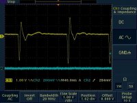
I first took an open voltage measurement of me tapping my finger on my bookshelf speaker cone. The cone moved in towards the box with the tap. The voltage waveform was recorded (Image 1, CH1) (Also, note the sound was very under damped, or resonant).
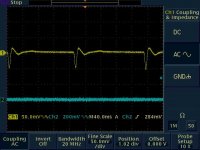
The second test was a voltage across a .2 ohm resistor across the speaker terminals (Image2, CH1) (Also note the sound was more transient, less resonant, a lot more damped). .2 Ohms was used, because it was as close a short as possible while still recording the voltage waveform).
A quick reality check:
Voc = Open circuit peak voltage of transient
VRs = Voltage across shorting resistor of peak of transient
Rs = shorting resistor ohmic value (.2 Ohms)
Then the speaker impedance (Zspeaker) should be close to:
Zspeaker = Voc - VRs / (VRs / Rs)
ZSpeaker = (2.25 - .05)/(.05 / .2) = 8.8 Ohms.
Nominally, the speaker is rated at 8 Ohms, so reality checks. (Surprisingly well considering the crudeness of the test.)
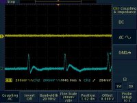
The third image is the output voltage of my amplifier with the same bump on the cone. Trace 1 is the output voltage of the amplifier, while trace 2 is the input voltage to the gate of my final output MOSFET. Note, how quickly the amplifier responded to keep the output voltage at 0 (matching the input voltage), thus the effect of negative feedback in the amplifier.
What is the output impedance of the amplifier, in this test? (I'm sort of reasoning this out, so if anyone has any input???)
What does all this mean? I Dunno, but my first thoughts are:
1. An amplifier with negative feedback will try to act as a short circuit to any energy imparted by the speaker cone into the voice coil. This should approximate a speaker with shorted terminals.
Keep in mind that while tapping on the speaker cone, not all of the energy went in to the voice coil. Much if it entered the air, as air was moved when the speaker cone was 'bumped'. I wouldn't even start to speculate on the ratio of energy into the air vs. the voice coil (Maybe some of you speaker experts could
2. The speaker impedance itself is the major hindrance to using
the voice coil to dampen any sound energy affecting cone.
3. Negative output resistance, should in effect, help to reduce energy imparted into the speaker, by 'guessing' at how much energy is really needed to counteract the transient waveform seen by the cone.
4. That I have way too much time on my hands, or that I need to learn to focus on my ongoing projects
-Dan
...and that means I won't make any progress on my amp today!!!
You have me wondering how negative feedback in an amplifier looks to a speaker.
I first took an open voltage measurement of me tapping my finger on my bookshelf speaker cone. The cone moved in towards the box with the tap. The voltage waveform was recorded (Image 1, CH1) (Also, note the sound was very under damped, or resonant).
The second test was a voltage across a .2 ohm resistor across the speaker terminals (Image2, CH1) (Also note the sound was more transient, less resonant, a lot more damped). .2 Ohms was used, because it was as close a short as possible while still recording the voltage waveform).
A quick reality check:
Voc = Open circuit peak voltage of transient
VRs = Voltage across shorting resistor of peak of transient
Rs = shorting resistor ohmic value (.2 Ohms)
Then the speaker impedance (Zspeaker) should be close to:
Zspeaker = Voc - VRs / (VRs / Rs)
ZSpeaker = (2.25 - .05)/(.05 / .2) = 8.8 Ohms.
Nominally, the speaker is rated at 8 Ohms, so reality checks. (Surprisingly well considering the crudeness of the test.)
The third image is the output voltage of my amplifier with the same bump on the cone. Trace 1 is the output voltage of the amplifier, while trace 2 is the input voltage to the gate of my final output MOSFET. Note, how quickly the amplifier responded to keep the output voltage at 0 (matching the input voltage), thus the effect of negative feedback in the amplifier.
What is the output impedance of the amplifier, in this test? (I'm sort of reasoning this out, so if anyone has any input???)
What does all this mean? I Dunno, but my first thoughts are:
1. An amplifier with negative feedback will try to act as a short circuit to any energy imparted by the speaker cone into the voice coil. This should approximate a speaker with shorted terminals.
Keep in mind that while tapping on the speaker cone, not all of the energy went in to the voice coil. Much if it entered the air, as air was moved when the speaker cone was 'bumped'. I wouldn't even start to speculate on the ratio of energy into the air vs. the voice coil (Maybe some of you speaker experts could
2. The speaker impedance itself is the major hindrance to using
the voice coil to dampen any sound energy affecting cone.
3. Negative output resistance, should in effect, help to reduce energy imparted into the speaker, by 'guessing' at how much energy is really needed to counteract the transient waveform seen by the cone.
4. That I have way too much time on my hands, or that I need to learn to focus on my ongoing projects
-Dan
Attachments
Re: Now you guys have me thinking...
I think basic output resistance can be measured by connecting one end of a resistor to the amplifier being measured, and the other end to a voltage source. That makes 2 resistances in total, and there should be a simple ratio of voltages.
Consider this:
If the amplifier keeps the voltage at the terminals of the speaker at exactly zero volts, how can any current be induced then? Somehow the voltage would have to vary along the length of the voice-coil, in a way that's consistent with it passing through a band of magnetic flux. An ordinary zero ohms output resistance amp only somewhat opposes movement of the voice-coil, by allowing only enough current to flow to keep the speaker's terminals at 0V. Much more current would flow and the mechanical damping factor would be much greater if it wasn't for the speaker's "parasitic" 8-ohm resistance, so instead of creating a speaker with no resistance, the next best thing would be negative output resistance.
CM
- Status
- This old topic is closed. If you want to reopen this topic, contact a moderator using the "Report Post" button.
- Home
- Amplifiers
- Solid State
- I want to make an amp with a Negative Output Resistance, but HOW??