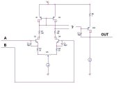
COnsider this circuit. A typical op-amp like conifguration. Could someone PLEASE explain to be which input is the inverting input and which is the non inverting input based upon which leg you take from the diff-amp???
I have seen circuit examples but I want an explanation. Thanks in advance!
I have seen circuit examples but I want an explanation. Thanks in advance!
Attachments
Addendum
Another question. Where is the best place to put DC offset trim? is R5 correct for this?
Thanks again in advance
Another question. Where is the best place to put DC offset trim? is R5 correct for this?
Thanks again in advance
Yes, R5 will trim the DC. With the input on the base, the collector output is inverted. Thus, if the base of Q2 is hooked to the collector of Q3, the output of Q2 is non-inverting when Q3 is the input. If Q4 was the input and Q2 hooked to its collector then the output of Q2 would still be non-inverting. If Q4 was the input and Q2 was hooked to Q3 the amp would be inverting. If Q3 was the input and Q4 hooked to Q2 the output would be inverting. For $6 AudioXpress will sell the Pass A40 circuit board which will allow you to experiment with this circuit. Or build an amp. I built a 250W/ch amp with a pair of these.
Probably the take off point for driving Q23 should be
below R1 or R2.
The non-inverting input will be the one whose collector
drives the base of Q23
below R1 or R2.
The non-inverting input will be the one whose collector
drives the base of Q23
Nelson pass wrote : "The non-inverting input will be the one whose collector drives the base of Q23"
Listen to him.
For r1 and r2, put them somewhere more usefull .. On the emitter of Q1 and Q2 to balance the currentmirror.
Sonny
Listen to him.
For r1 and r2, put them somewhere more usefull .. On the emitter of Q1 and Q2 to balance the currentmirror.
Sonny
Typical design
IIR, if you check my monster phono amp or my monster headphone amp you can get some idea of differential stages and design of a discrete opamp.
http://home5.swipnet.se/~w-50719/hifi/qsxm2/index.html
http://home5.swipnet.se/~w-50719/hifi/qrv01/index.html
IIR, if you check my monster phono amp or my monster headphone amp you can get some idea of differential stages and design of a discrete opamp.
http://home5.swipnet.se/~w-50719/hifi/qsxm2/index.html
http://home5.swipnet.se/~w-50719/hifi/qrv01/index.html

You might want to increase the value of R6. I hope this is not supposed to be a power amplifier.
Jocko
Jocko
Not supposed to be a power amp
It seems like what DJK and what NELSON PASS say conflict:
DJK:
. With the input on the base, the collector output is inverted. Thus, if the base of Q2 is hooked to the collector of Q3, the output of Q2 is non-inverting when Q3 is the input
NELSON PASS:
The non-inverting input will be the one whose collector
drives the base of Q23
Am I reading this correctly? Or should I goto bed now and read in the morning?
The current mirror is irrelevant. You can replace it with resistors if you like. Gain will drop, but there won't be any effect on the phase.
Actually, the inputs are labelled incorrectly. B is the non-inverting input. Look at it this way: The signal comes into the back side of the differential and appears at the collector out of phase. Then that signal is presented to the base of the output, which reverses it again. It is now back in phase with the input. Two phase reversals puts it back in phase.
Now, if you were to put a signal into the front of the differential, a different sequence of events takes place. The signal exits via the emitter, just like a follower..and, like a follower, the output is still in phase with the input. The thing to remember here is that as one emitter goes positive, the other must go negative; at all times the current drawn through the pair must remain constant. So, through this see-saw effect, the signal enters the emitter of the rear half of the differential out of phase with the input.
Still with me?
The signal then reverses phase going through the back half of the differential, then once more going through the output. It has now reversed phase three times, so it is out of phase with the input signal.
So, the way you've got it drawn, the front half of the differential is the inverting input, and the back half is the non-inverting input.
Don't let the phase reversal at the bottom of the differential trip you up. Just remember the see-saw; when one goes up, the other must go down.
Grey
Oops, I had two windows open so I could look at the drawing easily and sliced off the (3) from Q23. Each time I referred to Q2 as being the output I meant Q23. You really would be best to read the A40 article at the Pass site, it explains how to bias it up, the whole nine yards. Download the pdf file "The Pass A-40 Power Amplifier: by Nelson Pass " here: http://www.passdiy.com/legacy.htm then buy the boards here: http://www.audioxpress.com/
As regards your second drawing, "If Q4 was the input and Q2(3) hooked to its collector then the output of Q2(3) would still be non-inverting. " Q2 amended to Q2(3) as per above.
As regards your second drawing, "If Q4 was the input and Q2(3) hooked to its collector then the output of Q2(3) would still be non-inverting. " Q2 amended to Q2(3) as per above.
I believe the input polarity is reversed on your latest
picture, and what I really meant was that R1 and R2
should connect the Emitters of Q1 and Q2 to the positive
rail, and take the driver signal off the Collectors of the
input devices.
picture, and what I really meant was that R1 and R2
should connect the Emitters of Q1 and Q2 to the positive
rail, and take the driver signal off the Collectors of the
input devices.
Jocko Homo said:Glad it is not a power amp. You better increase R6 or Q23 will melt.
hehe... yeah that would be a good idea. i have melted transistors before and it is not cool. (no pun intended.) for me though it was a dumber mistake, i reversed the NPN and PNP devices in the complementary output stage of an amp. whoops.
- Status
- Not open for further replies.
- Home
- Amplifiers
- Solid State
- Inverting/non-inverting Op-amp Inputs !!!help!!!