ouch!
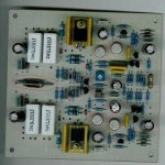
your inductor is a tad bit flimsy. Wind a larger one using larger gauge wire (use a pencil or whatever), then use the 2W resistor soldered AFTER you solder the coil in-place (maybe under the board). The whole output passes through the coil, the resistor is just for damping. Don't 'attach' the inductor to the resistor, make it the other way round.
No need to use a 5W resistor IMO.
It's best to heatsink the trannies, just for the sake of it.
You also should've left some space between the white 5w (emitter?) resistors and the board to allow some cooling in case it is needed.
Maybe the one in the pic is overkill, but why not?
Have any one tried replace those white ceramic resistors with thick film power resistors and listen for the sonic differences. I have replaced my passive crossover 5W white ceramic resistors with 20W Ohmite thick film power resistors same values with very positive result.
Regards,
Chris
Regards,
Chris
Dr. Leach had these instructions :
L1 - 10 to 12 turns #22 solid insulated wire wound tightly around R49 and soldered to the leads of R49 where they emerge from the resistor body. Click here to see an illustration. Solder one end of a piece of #22 solid wire to one end of R49. Wind the wire tightly around R49 to form L1. Clamp the windings to R49 with a small bench vise. Strip and solder the other end of L1 to R49.
What is the effect of using a thicker wire and also using more turns?
Thanks for reply
Wagener said:
What is the effect of using a thicker wire and also using more turns?
Sorry, did not mean to imply that you need more turns than specified.
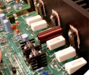
More turns will increase inductance - thus a decrease the amplifier's bandwith, this is generally not what you'd want to do, the pic was attached to give you an idea of how it's generally done.
Using larger magnet wire will allow for better power handling; the one you currently have should be enough for this kind of power output (<100W).
Q12 and Q13 are running class A at 4.2mA, if you run no more than ±70V then they will be running about 300mW, no sink required.
Q14 and Q15 are running in class A at 4mA and go into class AB above there. Considering the gain of the drivers and outputs, the shift to AB is probably above 100W/8R, I wouldn't worry about it.
The 2N3440/5415 will handle about 1W in 25*C ambient, up to 10W on a sink.
Q14 and Q15 are running in class A at 4mA and go into class AB above there. Considering the gain of the drivers and outputs, the shift to AB is probably above 100W/8R, I wouldn't worry about it.
The 2N3440/5415 will handle about 1W in 25*C ambient, up to 10W on a sink.
In my experience, the output inductor and resistor
work just fine as specified; the resistor won't
get warm in normal service as the coil has a far
smaller resistance. If it ever gets really hot,
there's something wrong with the amplifier
(probably oscillation).
I used heatsinks on the TO-5 transistors when I
could fit them without danger of touching an
adjacent transistor or heatsink. This isn't always
possible, depending on layout, and in practice I
found that it was never really necessary, either.
They get rather warm, but never really too hot.
On my latest iteration, I used some IRC .27 ohm
wirewounds that seemed more robust than the
sandcast variety, and probably have a better
temperature coefficient. Mills resistors would be
very good here especially since they're available
in tighter tolerances and are non-inductive and
non-magnetic.
My ideal would be bulk metal foil resistors (with
heatsinks), but suitable units are very expensive
indeed.
More important to closely match the resistors and
transistors in the input stage as closely as possible,
and the zeners, too. I used Black Gate electrolytic
caps in the input stage and feedback, but that's as
far as my budget would go.
If I could, I would use bulk foil resistors and Black Gate
electrolytics everywhere and other premium parts,
but I'm very happy with the sound of the newest
boards and doubt it could be audibly improved upon
given the quality of the rest of my system.
Been building and using Leach's amplifier design since
the late 70's. They aren't pretty to look at, but
they work reliably and sound very good. Some time
I'll get some pictures to put online to show how I
built mine.
Wagener said:the silver transistors (2N3440 and 2N5416)
also the output filter resistor is a (2W) as specified by Dr. Leach. Is this big enough?
What would the difference be in using a wirewounded 5W resistor in place of the 2W ceramic resistor.
hi
do you have schematic ?
thx
Re: Re: do I need to heatsink these?
I think they're talking about this:
http://users.ece.gatech.edu/~mleach/lowtim/
UltimateX86 said:
hi
do you have schematic ?
thx
I think they're talking about this:
http://users.ece.gatech.edu/~mleach/lowtim/
With the 5W ceramic potted WW resistors, they are best mounted upside down as most heat escapes from the open side AND the case is held on if the thermal cycling loosend the bond to the pot. Numbers down. Not the prettiest.
I would put a radial fin heatsink on those two Vas drivers as they will appreciate the extra power handling in reduced Vbe shifts - better bias stability. They might be quiescent at only 300mW but they cycle up to twice that in a pkg rating of about 1W?
I would put a radial fin heatsink on those two Vas drivers as they will appreciate the extra power handling in reduced Vbe shifts - better bias stability. They might be quiescent at only 300mW but they cycle up to twice that in a pkg rating of about 1W?
- Status
- This old topic is closed. If you want to reopen this topic, contact a moderator using the "Report Post" button.
- Home
- Amplifiers
- Solid State
- do I need to heatsink these?