Hi All-
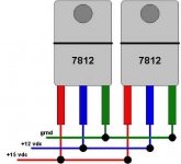
I was curious about what would happen if you paralleled voltage regulators to try and get more current availability for a circuit.
I did a search and did not find any drawings such as below or this specific question being "recently" discussed. I was not about to read search results going back 50 yrs (exaggerating of course).
Thanks in advance,
Troy
Attachments
I most probably won't work. Since two devices are never
exactly identical they will fight each other and share the
current unequally. I would even be worried about oscillations
due to the mutual independent feedback loops.
There has been suggestions before on the forum to parallell
regulators by adding series resistors at their outputs. That
might work, but regulation will suffer.
I agree with Christer. I think it might work with 317-type (or other with external feedback network) regulators, by including a small sub-ohm (depending on current drawn) equalising resistor and taking the feedback point for all regulators at the load point where the equalising resistors come together.
Jan Didden
Jan Didden
You might wanna look into the datasheets of the IC´s as there is extensive information about these applications.
As Christer said your circuit won´t work very reliable but some chips from Linear Technology for example (LT1083) just need very low ballast resistances on the output (like 0.015Ohm) to share current equally.
They are more expensive of course.
You´ll also find application notes from National Semiconductor, Linear Technology about voltage regulators which are very interesting reads.
You also get voltage regulators up to 10A but it depends on your application if you can get away with it.
Maybe you´re doing it to spread power dissipation between the IC´s?
Hi All-
Well I'm building a pwr supply box for a friend who has six(6!) 9 volt wall warts powering up his guitar pedals.
I got a transformer, bridge, plenty of filter caps and 4 7812 regulators. Instead of having 4 separate circuits for each regulator(2 pedals per each 1 amp regulator) I was looking into just paralleling the 4 7812's to see if I could get them to split the 4 amp load.
I guess it would be safer to have the separate circuits for each regulator.
Not critical circuits or anything. By the way, all of the pedals have an operational range of 9-15 volts DC.
Thanks again,
Troy
One of the best and most popular ways to achieve greater current output of a regulator, is to use parallel emitter current followers on the output.
I don't have any schematic drawing software handy, however, there are many good examples on the internet, and probably many users here at diyaudio that could provide a simple example.
Essentially, the output of a positive regulator will connect to the base of an NPN transistor, with the unregulated DC voltage input also going to the collector of the transistor, and the emitter being the new output. It works on the principle of maintaining vbe drop across the transistor. The ouptput will now be about .5 to .8 volts lower than the original regulator output, so it's nice if you have a variable regulator like a 317 so you can set the desired output.
This may be a bit confusing, but if someone shows a diagram, it'll all clear up.
Have you looked at the specifications of the pedals?
Usually they use currents much below 100mA each.
I used them myself but the only one that´s left is a tube pedal consuming up to 400mA but that´s the tip of the iceberg.
With 200mA per pedal that would sum up to 1.2A.
I´d use just one 1.5A, 2A, or 3A regulator (LM317,L200, LM350.....) depending on your needs.
Important is that the power supply is absolutely quiet so proper bypassing and enough capacitance is required.
If you have the 7812 around and really need more than 1A you could also use one 7812 for 1 (or2) pedals.
This way you don´t need to worry about current sharing the whole load.
If regulation is really not all that important, you might just try a filtered, unregulated supply and see if your pal likes the sound... get a 9 volt transformer and put a bridge rectifier and maybe 10,000uF on the output of the bridge... three parts, one small package, you're done in an hour.
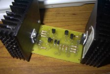
I'll post pics when finished..
This supply will have 10 & 12 volts AC, +/- 5, 9, 12 and 15 volts DC.
But since the majority of the load requires +12 volts, I was just looking to see if paralleling the 7812's would be better.
Obviously not, so I will stick with the 2-3 7812's as standalone circuits.
THANKS!! To all the people who took the time to comment.
Troy
Parralleling regulators can work (note I write "can" not "will"). I know this because I did it once and had no problems. However, I lucky, I could just hsave easily sent one or more regulators up in smoke. One more example of how amazing things can be accomplished through ignorance.
Faced again with the same problem, I would use the circuit shown by Hoffmeyer (above) as blind luck is a sub-optimal approach to these things.
Faced again with the same problem, I would use the circuit shown by Hoffmeyer (above) as blind luck is a sub-optimal approach to these things.
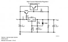
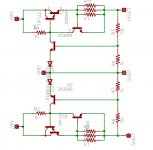
Why don't you go all discrete. This is a popular regulator I found many moons ago, it was only positive but I made up the negative side and it works vary well quite high regulation for it's simplicity. It has short circuit protection which is adjustable by varying r7 and r5. Voltage is also adjustable up and down by replacing r9 and r10 with 20k pots.
Cheers,
Cheers,
Attachments
rabstg said:Hi All-
I was curious about what would happen if you paralleled voltage regulators to try and get more current availability for a circuit.
I did a search and did not find any drawings such as below or this specific question being "recently" discussed. I was not about to read search results going back 50 yrs (exaggerating of course).
Thanks in advance,
Troy
i have tried using two 7805's in parallel and it works, i put a 0.22ohm 2watt resistor at the output terminals of each ic...i use the setup to test atx psu's that have busted 5v standby cicuits to see if the rest of the circuit works....
- Status
- This old topic is closed. If you want to reopen this topic, contact a moderator using the "Report Post" button.
- Home
- Amplifiers
- Solid State
- parallel voltage regulators to increase current?