Hi,
I have some questions for you guys. I am in the process of building a rather large class AB MOSFET amp right now, and the man who is teaching me (ex-engineer for Soundstream Audio...years back) has left me with a few questions that I could not get the answers for...so I'll try here.
Here goes:
1. I understand that the A and B classes are seperated by their bias levels. What exactly is biased up and why does it help? What is biasing (I have an idea, but would like to get it confirmed)? Class A is biased to such an extent that the power devices are always conducting the amount of energy that the amp is rated for, hence a 10W class A is always sucking 10W and dissipating heat. Class B is not biased, and the power devices only conduct when a signal is being reproduced, hence the power consumption varies, the amplifier is more efficient, but distortion goes up (WHY?). Class AB is simply a class B that is biased up to take care of most of the distortion, but still is rather efficient. Do I have this all right?
2. He is showing me elaborate temperature-compensation circuits. I understand that we need to correct for the output devices as they change temperature, but what are we altering as temp goes up? Are we changing the bias level? I am really confused on this...
I know these questions might seem rather simple to you guys, my mentor did not understand what I was asking him for and I did not want to push it with him today.
Thanks,
Matt
If i understood your question
When temperature increase, transistor internal resistance decreases, this way more current flow and more heat is generated.
This way, having more heat, transistor internal resistance becames lower and lower, this way, current flow increase more and more, the resultant is more and more heat generated.
When enormous temperature took place in your heatsinks and transistors, their resistance will reduce more and more again... this way current will increase agains.....increasing the heat another time....this way....if this automated mechanism is not sttoped everything will melt, transistor will melt and will have a internal short circuit, fuses will burn and amplifier will be damaged.
Normally, some diodes are used to control the bias.... when cold you adjust your amplifier to, lets say, 50 miliamperes, and you check if this current is enough to maintain a dc voltage between base and emitter around 550 or 600 milivolts. with this voltage transistor is on and the small current will passes in direction of ground patch througt the speaker or sometimes throught the other transistor. those diodes are conected to maintain 600 milivolts over each one of them, this way if you need 1.2 volts between PNP and NPN output transistors (sometimes drivers transistors) you will use two diodes in series... if needed a little bit more voltage, a small variable resistor (100 ohms, 200 ohms or 500 ohms trimpot) in series with those diodes.
Those diodes and resistor maintain the enough voltage (potencial diference measured from one base to another, from pnp base to npn base) to keep 550 to 600 milivolts between base and transistor emitter, and current passing will be 50 miliamperes.
The Key is that "those diodes, as a semiconductor, reduce their internal resistance when temperature increase), this way you made it touch heatsink, or put it inside heatsink holes drilled with same diameter...hard to enter, or glued in place).... temperature now will increase, amplifier is working and pushing hard!.... heatsink becomes hot, bias diodes too, this way, bias diodes resistance becomes lower and lower, the voltage measured on diodes (directly on them, multimeter plus and minus on diodes extremes) will reduce....not more 600 milivolts....now 500 milivolts....each one..... from npn base to pnp base not more 1.2 volts, now you have something around 1 volts..... a little bit more because of variable resistance in series (the adjustment trimpot).... this way, the output transistors, receiving less DC voltage from base to emitter conduct less current.... and less current represents less heat....an automated control.
Sometimes no diodes, people use transistor to make this job, the unit is conected from base to colector and base to emitter in a manner that turns into a variable resistor..... one of the base resistor is a variable one to adjust the "quiescent" point, and this is the "stand by" current adjusted, called bias...... this is made with no signal input... and with a charge in the output... a 8 ohms resistor or a speaker.....the transistor, beeing a semiconductor also reduces colector to emitter voltage when very hot....making the same work... this bias, adjusted in stand by..... in iddle.....when no signal is beeing amplified, also took effect when audio cames from input....more bias more current and heat...less bias less current and heat..... the other effect, made with the audio, is the one we want to happens....because more audio, more conductance ....less audio...less conductance and this makes our audio.... variating voltage that came from the power supply..... variations taken on output emitters.
I am not a english language people.... despite poor english i can help because this is the second step to understand amplifiers...maybe third....first is to understand deeply how transistor works and how to calculate their voltages (ohms law), second is to understand when you connect other transistor, colector from first to base of the second (as an example), how to calculate this "small system" and understand what will happen in the next stage.... and third step is understand this automated bias control.
More sittuations as capacitances, parasitics oscilations.... sorry.... this is already magic to me.
I speak portuguese, this way, sorry.... can write something wrong and this can became a wrong meaning, sometimes offensive.... is not written with this purpose.
Carlos
Sorry, i forgot one question
Why class b distorts?
Because without audio transistor is off.... is cutted...no current will flow....if you measure from base to emitter you will find,....lets see..... 400 milivolts.... this way he is off....nothing will conduct from colector to emitter.
But, when hard audio enters...high level of constant Radio Frequency, or continuous audio tone.... this audio or RF voltage alternated is added to those 400 milivots and transistor starts to work!... he will conduct big amounts of energy.... and with constant good level audio..... it will work the same quality as AB.
The problem with AB class is because audio is not a constant level signal (related to ac voltage peaks).... you have low level ments,and on this moments transistor cut, and microseconds latter will be on again... this makes some "click" noise.... something alike..... on both NPN and PNP output and drivers.... or only in drivers, in output units, because normally all others are in class A or AB and will not suffer from audio variations the same way output suffer..... output is connected and disconnect too many times...audio becames bad... distorted in low volumes .... normally is used in radio frequency units that receive continuous high level signal that produces the needed voltage between base and emitter.... keeping transistor on..... when working.... with signal..... current passes always..... alike class A or class AB.
Carlos
A real-life class B cct is biased on just a few milliamps, but you will find that transistors and mosfets are a bit lazy when they are just beginning to turn on a little bit. The base signal tells it to move a certain amount but the emitter doesn't quite follow it the full distance. When they are conducting maybe an amp or so they are much better behaved.zagisrule! said:Class B is not biased, and the power devices only conduct when a signal is being reproduced, hence the power consumption varies, the amplifier is more efficient, but distortion goes up (WHY?).
With a class B cct the upper transistor handles the top half of the wave and the bottom one the lower half. The tricky part is handing over from one to the other because both transistors must pass through their low-current region - the area where so-called "crossover distortion" occurs. Makes the sound kind of fuzzy and gritty at low volumes. Class A doesn't have this problem.

Mmmm.... class A.
/Circlotron - has a 50+50W class A
")
Wonderful!
It is very clear to me now what the temperature compensation is and how it works. I greatly appreciate the time you took to explain to me the concept behind that destroyer X.
The class B distortion makes tons of sense now too...because the transistor turns itself off and takes too much time to turn back on as the wave passes through...I can see why class A is the best in regards to quality.
Some more questions now:
What are some typical distortion rates for a "textbook" type amplifier of class B? Class A? I know these vary alot with transistor selection, schematic, and more, but if we were to use the same basic circuit with different bias amounts, what kind of a difference would we see in distortion? I assume that class AB will fall in between the two classes, what is the relationship of biasing to distortion? Linear?
I need some rather large MOSFET's, for 100-150V, preferably in the TO-3P/TO-247 package for my new amplifier. I was considering a Hitachi series of FET's, I forger the name, but they were a matched audio pair (N and P channel's complimentary) and I can't find them anywhere for hobbiests to purchase. Where can I purchase a couple of these Hitachi units at reasonable prices? If not, can you suggest another set of complimentary N and P channel units good to +/- 100V or more?
Because you have me very interested in this much less distorted class A, I am considering lowering output power level in favor of true class A operation. I will be driving a 6 ohm load most of the time, amd I still have a chance to change the rail voltages before I order the transformer. I would like to be able to run true class A at limited power levels so I can use the same MOSFET's, heatsink, and hopefully power supply. Then I could change the bias and try running the amp at different bias levels to see what difference I can detect or see on the oscilloscope. I would likely run class AB most of the time, I just want to have the option of running A for experiments. What is the best way to go about this? Perhaps a way to lower my rails from my intended +/- 50V or so to +/- 20V to limit power, but I don't know how to do this. My budget is fairly limited, so another transformer is out of the question unless the lower VA models cost considerably less.
Thanks again for all your help...this is looking like a new hobby for me!
Mmmm...class A
-Matt
hi zagi
im new to DIY too...i am sure that im not 100% right, but i hope to learn from this forum, so i an happy if anyone corrects my mistake...for the transistor..you might want to try On-Semi..they have a samples program where you can get 25 of each type of transistor..you pay for shipping only..which i think is fair..they have equivalents to the Hitachi's i believe...
2nd...to make your amp..maybe you should make a pure class A, because you can always make the class A go to class AB if the PSU cannot supply the peak current needed to drive the amp in class A (you will need to make sure your drivers have a switch off capacitor attached for faster turn off)...some formulas to explain myself here
P(RMS/ave) = (Vpeak)squared/2(Rload)
Vpeak = Vrail + 10V (approximately), to accomodate losses
Ipeak = Vpeak/Rload
NOW to stay in class A, your amp wil have to supply 2xIpeak. beyond this it will leave
correct me if im wrong please...im here to learn
BTW
some books of interest
Randy Slones Power Amplifier book, Nelson Pass articles (the mans a genius...very well written too)..Erno Borbely's articles...and ofcourse D Self's book (which im trying to get second hand..anyone want to sell theirs??)
im new to DIY too...i am sure that im not 100% right, but i hope to learn from this forum, so i an happy if anyone corrects my mistake...for the transistor..you might want to try On-Semi..they have a samples program where you can get 25 of each type of transistor..you pay for shipping only..which i think is fair
..they have equivalents to the Hitachi's i believe...2nd...to make your amp..maybe you should make a pure class A, because you can always make the class A go to class AB if the PSU cannot supply the peak current needed to drive the amp in class A (you will need to make sure your drivers have a switch off capacitor attached for faster turn off)...some formulas to explain myself here
P(RMS/ave) = (Vpeak)squared/2(Rload)
Vpeak = Vrail + 10V (approximately), to accomodate losses
Ipeak = Vpeak/Rload
NOW to stay in class A, your amp wil have to supply 2xIpeak. beyond this it will leave
correct me if im wrong please...im here to learn
BTW
some books of interest
Randy Slones Power Amplifier book, Nelson Pass articles (the mans a genius...very well written too)..Erno Borbely's articles...and ofcourse D Self's book (which im trying to get second hand..anyone want to sell theirs??)
Re: Wonderful!
If you want to use lateral mosfet pair 2SK134 and 2SJ49, TO-3, they are rated at 140V (7A). I bought spare ones on ebay by Soundvalves member at 49$ US for 2 matched pairs (4 transistors total).
If you really want to use TO-3P, then Borbely audio sells matched pairs of (160V, 7A) 2SK1058 and (180V, 10A) 2SJ162 or 2SK1529 and 2SJ200 at http://www.borbelyaudio.com/index21.htm. I did not use Borbely sales services though so I can not comment.
zagisrule! said:...I need some rather large MOSFET's, for 100-150V, preferably in the TO-3P/TO-247 package for my new amplifier. I was considering a Hitachi series of FET's, I forger the name, but they were a matched audio pair (N and P channel's complimentary) and I can't find them anywhere for hobbiests to purchase. Where can I purchase a couple of these Hitachi units at reasonable prices? If not, can you suggest another set of complimentary N and P channel units good to +/- 100V or more?
-Matt
If you want to use lateral mosfet pair 2SK134 and 2SJ49, TO-3, they are rated at 140V (7A). I bought spare ones on ebay by Soundvalves member at 49$ US for 2 matched pairs (4 transistors total).
If you really want to use TO-3P, then Borbely audio sells matched pairs of (160V, 7A) 2SK1058 and (180V, 10A) 2SJ162 or 2SK1529 and 2SJ200 at http://www.borbelyaudio.com/index21.htm. I did not use Borbely sales services though so I can not comment.
I will check ON-semi for a comparable set, thanks for the tip.
As for your calculations, I think we calculate power by V^2 / Rload (very possible that I am wrong)...the current calculation might make sense, we are always dissipation whatever power, to produce a full wave we would need twice that...makes sense
fab: thanks for the links, I'll have a look.
I am also building the pre-amp, could anyone suggest a good audio op-amp? I'll run 15-18V rails in the preamp, and will need several of them for the active crossovers. I plan to seperate the signal into three bands, then use digital pots to determine freq strength, and re-combine with another op-amp, and amplify for the power amp with another. This requires 4-5 units per channel, so a dual unit would be nice. I am going to drive all of this with a PIC, which I have experience programming already. Should make for one sweet unit! I would do more bands if it was easier to seperate them...perhaps there is a better way to do bandpass filters than using op-amps?
-Matt
Very interesting Jagsrule.
I think your name is not correct... sorry, next time i will take another look....Jagisrule maybe.
I really cannot talk about FETs, i am so stupid related to them that i can think it can bite my finger (kidding)
About class AB.... is like iddle rotation of automobile motors.... stand by situation....i suppose (not sure) transistor is not in his linear region... this way, problems may ocurr.... i know that bias can make the amplifier give 2 or 3 watts in class A...but not a really class A, because transistors will not be linear.
But is economical and very efficient... almost 65% of the entire energy is transformed into real audio....only 35 percent in heat.... depending of the volume, the audio voltage inside amplifier, it will go into linear region.
Class A makes you cry.... emotion....music appear so close to you, if you like the girl singing you may give a step forward in her direction (in the reallity going near the speaker).... voices so present.... also clear.... positions, yes, you can detect where are the man playing bass..... wheres the other instrument....no comparison...no amplifier i already heard (52 years old) can reach class A quality.
Also, is not a stupid circuit, full of transistors, when you know that each one distorts a little, this way, as much you have, worst result will be obtained.... this way people say that the best thing is a wire with gain.... amplifier perfect..... we do not discover how to do this one.... Fets is interesting because no many stages...but can bite me....i am afraid of it... whe always afraid of the things we do not know.
Class A is inefficient..... something alike 20 percent... when you have one transistor doing whole job.... when push pull the thing became better....may be 30 percent.... or 40..... and if you think in peak to peak music power, or instantaneous low time bursts... can be better. Always a heatter in your house.... small units are putting 70 watts of heats out to give you small power....less than 10 watts clean.
The Death of Zen, you will find in Rodd Elliot ESP pages are wonderfull, incredible, magnificent,astounding, astonishinghy and marvellous... and there are many others based in John Lindsley Hood that died last year i think...not sure, maybe a death aniversary... those amplifiers, JLH called, because first John Letters are very good an simple and cheap to construct, using 2N3055 that can be found costing a dollar somewhere... also you can put two TIP41 in parallel to make one 2N3055 and spend around a dollar too....and whole forum likes and hundreds where constructed, and when people ask to us to shown our preferences, always one of those class A appear many times...beeing very well voted.
I Strongly recomend you start with that one.
Problem is that it needs 24 volts, not simetrical voltage with clean 2 ampéres (not sure)... and produces around 6 volts of audio.... 4 to 5 watts rms... they can go to 10 watts, but not too clear in my point of view.... and, do not ask me why, 5 class A watts is not the same as 5 class AB watts.... that's stupid, absurd, crazy, ...but is what we feel... do not make any sense...but a lot of people has courage to say that crazy thing.... i am saying too.
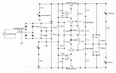
Some people uses enormous condensers to filter..... can make a power supply.... i have an old circuit, using since sixties, was from a Ampex Video tape Machine.... a monster machine... i will put the schematics here.... simetrical control of your 50 volts dc plus and minus.
Other questions, in the reality, compared to magnificent engineers that sometimes appear and put ligth in our darkness, i am a beginner.... 30 years assembling schematics without try to think how they works...now i am understanding a little.
I am opening to other people help you, because all i can do was done.....your answers becaming hard to me, i cannot help you.
this way i will silence and hear people better prepared.
You always welcome to ask....but i am afraid can not go so far.
Carlos
I think your name is not correct... sorry, next time i will take another look....Jagisrule maybe.
I really cannot talk about FETs, i am so stupid related to them that i can think it can bite my finger (kidding)
About class AB.... is like iddle rotation of automobile motors.... stand by situation....i suppose (not sure) transistor is not in his linear region... this way, problems may ocurr.... i know that bias can make the amplifier give 2 or 3 watts in class A...but not a really class A, because transistors will not be linear.
But is economical and very efficient... almost 65% of the entire energy is transformed into real audio....only 35 percent in heat.... depending of the volume, the audio voltage inside amplifier, it will go into linear region.
Class A makes you cry.... emotion....music appear so close to you, if you like the girl singing you may give a step forward in her direction (in the reallity going near the speaker).... voices so present.... also clear.... positions, yes, you can detect where are the man playing bass..... wheres the other instrument....no comparison...no amplifier i already heard (52 years old) can reach class A quality.
Also, is not a stupid circuit, full of transistors, when you know that each one distorts a little, this way, as much you have, worst result will be obtained.... this way people say that the best thing is a wire with gain.... amplifier perfect..... we do not discover how to do this one.... Fets is interesting because no many stages...but can bite me....i am afraid of it... whe always afraid of the things we do not know.
Class A is inefficient..... something alike 20 percent... when you have one transistor doing whole job.... when push pull the thing became better....may be 30 percent.... or 40..... and if you think in peak to peak music power, or instantaneous low time bursts... can be better. Always a heatter in your house.... small units are putting 70 watts of heats out to give you small power....less than 10 watts clean.
The Death of Zen, you will find in Rodd Elliot ESP pages are wonderfull, incredible, magnificent,astounding, astonishinghy and marvellous... and there are many others based in John Lindsley Hood that died last year i think...not sure, maybe a death aniversary... those amplifiers, JLH called, because first John Letters are very good an simple and cheap to construct, using 2N3055 that can be found costing a dollar somewhere... also you can put two TIP41 in parallel to make one 2N3055 and spend around a dollar too....and whole forum likes and hundreds where constructed, and when people ask to us to shown our preferences, always one of those class A appear many times...beeing very well voted.
I Strongly recomend you start with that one.
Problem is that it needs 24 volts, not simetrical voltage with clean 2 ampéres (not sure)... and produces around 6 volts of audio.... 4 to 5 watts rms... they can go to 10 watts, but not too clear in my point of view.... and, do not ask me why, 5 class A watts is not the same as 5 class AB watts.... that's stupid, absurd, crazy, ...but is what we feel... do not make any sense...but a lot of people has courage to say that crazy thing.... i am saying too.
Some people uses enormous condensers to filter..... can make a power supply.... i have an old circuit, using since sixties, was from a Ampex Video tape Machine.... a monster machine... i will put the schematics here.... simetrical control of your 50 volts dc plus and minus.
Other questions, in the reality, compared to magnificent engineers that sometimes appear and put ligth in our darkness, i am a beginner.... 30 years assembling schematics without try to think how they works...now i am understanding a little.
I am opening to other people help you, because all i can do was done.....your answers becaming hard to me, i cannot help you.
this way i will silence and hear people better prepared.
You always welcome to ask....but i am afraid can not go so far.
Carlos
Attachments
Thanks for your help Destroyer X.
So you are saying that true class A is really superior in sound quality to class AB. I am pretty much settled now that I should build both a class AB and a pure class A. I wanted the AB to be a monster, for 200W or more, for parties and such (going to college soon ), but it sounds like another amp would be great to have for my room and just listening to most of the time. A lower power unit such as the one you suggest (10W or so RMS would be good) would allow me to build the unit relatively inexpensively, because a smaller transformer could be used, as well as a moderately-sized chassis. Look at what you all are doing to me! Now I am into even more amplifiers, I will probably have dozens made in the next few years.
At least it is a good hobby to be into, and I can do productive things with it.
One more question now, I went to ON semi and they have no comparable MOSFET's to the Hitachi units I was originally considering. Either I would have to parallel multiple TO-220 units (I'd really rather not) or I could use bipolars for the output stage. Why do they have so much more variety in the bipolar region? They have dozens of audio-transistors, but nothing for audio MOSFET's? I understand that that is because commercially noone uses the MOSFET's in amps, but why not? Why would all the commercial manufacturers use bipolars?
Time to get cracking looking for the best small class-A out there. And the suitable chassis and heatsinks for it as well.....
-Matt
So you are saying that true class A is really superior in sound quality to class AB. I am pretty much settled now that I should build both a class AB and a pure class A. I wanted the AB to be a monster, for 200W or more, for parties and such (going to college soon
), but it sounds like another amp would be great to have for my room and just listening to most of the time. A lower power unit such as the one you suggest (10W or so RMS would be good) would allow me to build the unit relatively inexpensively, because a smaller transformer could be used, as well as a moderately-sized chassis. Look at what you all are doing to me! Now I am into even more amplifiers, I will probably have dozens made in the next few years. At least it is a good hobby to be into, and I can do productive things with it.
One more question now, I went to ON semi and they have no comparable MOSFET's to the Hitachi units I was originally considering. Either I would have to parallel multiple TO-220 units (I'd really rather not) or I could use bipolars for the output stage. Why do they have so much more variety in the bipolar region? They have dozens of audio-transistors, but nothing for audio MOSFET's? I understand that that is because commercially noone uses the MOSFET's in amps, but why not? Why would all the commercial manufacturers use bipolars?
Time to get cracking looking for the best small class-A out there. And the suitable chassis and heatsinks for it as well.....
-Matt
HELP FRIENDS!, I really know nothing about FET or MOS FET
Really, do not know nothing related FETs.
Your idea related amplifier AB to shake your house is very good, and a real clean class A to be happy.
I am using 3 amplifiers with passive filter in the input.... one for bass, other for mid and other for Highs.
No condenser or inductors between amplifiers and speakers.
This way, amplifiers are not confused with so many informations same time..... an order to go ahead strong to make bass, same time another wave over that ordering speaker go down softly to reproduce voice, same time other order to small an hi frequency movement to have the bells and metal sounds.... so, speaker is alike a blind man in the middle of hard combat...bullets making noise near your ears and you do not know where to go.... thats what amplifier and speaker feel.
This way, i separate them, the way we make with our children not to figth..... a new sound appear.
Field effect is Nelson Pass and Mister Hugh from Aksa matter, i know others but those are easier to remember.
Carlos
Destroyer:
It is my time to help you now!
FET = Field Effect Transistor
MOSFET = Metal Oxide Semiconductor Field Effect Transistor
JFET = Junction Field Effect Transistor
A FET is a voltage controlled device (Bipolar Junction Transistors are current controlled), and because of their voltage-sensative input, are high-impedance devices. This makes them suitable for many purposes where BJT's would not work...that is why very high-impedance op-amps or other amplifiers use FET or JFET inputs...because then they can sense the very low-current signals that BJT's would not recognize or detect. The resistance from "drain" to "source" (equivilant to BJT "collector" and "emitter") is directly controlled by the voltage of the input, hence making them voltage-controlled resistors of a sort.
A MOSFET is a high-current version of the FET, that uses a metal-oxide coating to separate the source and the drain. This very thin coating allows the MOSFET to have an extremely low on resistance (hence less heat dissipated and greater efficiency). Most industrial applications for MOSFET's are to switch high power loads, becuase the low on-resistance of the MOSFET makes it extremely efficient compared to BJT's.
So, the high input impedance, low on resistance, and characteristics with applied voltage to the gate (equivilent to the "base" of a conventional transistor) make them suitable for many designs.
Because of their different principles of operation, you can usually not just drop a MOSFET into a BJT circuit and expect it to work.
Hope that this helps you out a bit!
-Matt
While I have not done this myself due to too many other incomplete/pending projects, anyone who is really curious about Class A vs. B performance and sound might take a look at Doug self's "Trimodal" amplifier which can be switched between A an B (AB as well I think). Frankly, I don't see it as an amplifier for practical use, for one thing the schematic is pretty complicated but it looks like an interesting investigation. You can even get PCB (pricey) at http://www.signaltransfer.freeuk.com/
Bias is the CURRENT flowing through the amplifying device in the absence of an input signal.1. I understand that the A and B classes are seperated by their bias levels. What exactly is biased up and why does it help? What is biasing (I have an idea, but would like to get it confirmed)?
Bipolars, FETs, tubes all have non-linear transfer functions whether you are talking about current gain (beta) or voltage to current gain (transconductance Gm). Applying bias current usually reduces distortion as a % of the input signal for a given size of input signal.
All devices can be analyzed as beta or Gm devices but it is usually easiest to consider bipolars as current gain devices and FETs as transconductance devices.
Bipolars operate in minority charge carrier mode and require a current flow into the base to promote conduction between collector and emitter. FETs work electrostatically: a voltage field varies the depletion region width and allows conduction. FETs are a majority carrier device.
In textbooks you'll read that bipolars have an exponential beta curve and FETs have a square-law transconductance curve. This is not true for power devices (as Charles notes) so you cannot assume this. With small devices at small currents you can assume a bipolar transconductance is about 40Ic but this does not hold true for high current devices.
In either case, when a datasheet talks about "complementary" devices it is exaggerating the truth. It is impossible to make an electrical opposite of either device in all characteristics because there are no positrons. This is why there are no p channel vacuum tubes. The few parameters which the mfr uses to say something is complementary are unlikely to be relevant for audio even if they say so (engineers working for transistor companies have the same eductaional background as other engineers and this almost never includes audio).
MOSFETs: hard to destroy due to lack of secondary breakdown
Tend to be more capacitive
Tend to have higher DS resistance and lower Gm
Simpler to parallel up
Lower drive currents required at audio frequencies
Commercially mostly used for switch mode psus
BIPOLARS: easier to destroy
Tend to have lower capacitance and higher Gm
Higher drive currents required at audio frequencies
- Status
- This old topic is closed. If you want to reopen this topic, contact a moderator using the "Report Post" button.
- Home
- Amplifiers
- Solid State
- Questions