here's mine:http://gallery44059.fotopic.net/p2774837.html
http://gallery44059.fotopic.net/p2774836.html
http://gallery44059.fotopic.net/p2774837.html
http://gallery44059.fotopic.net/p2774840.html
http://gallery44059.fotopic.net/p2774838.html
http://gallery44059.fotopic.net/p2774841.html
http://gallery44059.fotopic.net/p2774839.html
http://gallery44059.fotopic.net/p2774836.html
http://gallery44059.fotopic.net/p2774837.html
http://gallery44059.fotopic.net/p2774840.html
http://gallery44059.fotopic.net/p2774838.html
http://gallery44059.fotopic.net/p2774841.html
http://gallery44059.fotopic.net/p2774839.html
Hi Jon,
Yes I etched the PCBs myself using the equipment available at the school I studied at when I build the amp.
I was running the amp at about 100W idle for each of the four channels; however I could not perceive any difference when changing this to about 30W so this is the current (no pun intended) it’s now set at.
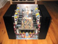
I made some modifications by adding three extra sets of output transistors, and changing the input small signal transistors to BC546/556 because these are commonly available here in Denmark.
The rest of the transistors are:
MJE340/350 for VAS and predrive stage.
MJE15032/15033 for driver stage.
MJL3281/1302 for output.
I noticed a lot of questions from Wagener regarding this amp I hope you don’t mind me answering here where more people can read it and hopefully use it.
The caps I used are almost all PP (Polypropylene) or PE (Polyethylene) types, except for the supply decoupling caps witch all are some form of electrolytic that I had I in stock.
The only ceramic caps I used are the ones used in the VAS stage for stability and the one in the feedback compensation network.
I used a large NON polarised electrolytic (470 µF) caps for input DC block, and another for the feedback cap that sets the low cut off frequency.
I hope this helps.
\Jens
Yes I etched the PCBs myself using the equipment available at the school I studied at when I build the amp.
I was running the amp at about 100W idle for each of the four channels; however I could not perceive any difference when changing this to about 30W so this is the current (no pun intended) it’s now set at.
I made some modifications by adding three extra sets of output transistors, and changing the input small signal transistors to BC546/556 because these are commonly available here in Denmark.
The rest of the transistors are:
MJE340/350 for VAS and predrive stage.
MJE15032/15033 for driver stage.
MJL3281/1302 for output.
I noticed a lot of questions from Wagener regarding this amp I hope you don’t mind me answering here where more people can read it and hopefully use it.
The caps I used are almost all PP (Polypropylene) or PE (Polyethylene) types, except for the supply decoupling caps witch all are some form of electrolytic that I had I in stock.
The only ceramic caps I used are the ones used in the VAS stage for stability and the one in the feedback compensation network.
I used a large NON polarised electrolytic (470 µF) caps for input DC block, and another for the feedback cap that sets the low cut off frequency.
I hope this helps.
\Jens
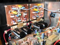
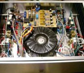
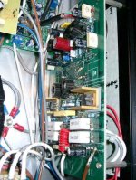
Here is my version:
The PCB is in fact a Double Barrel Amp, modified to the Leach circuit. Power transformer is a Plitron 600VA, 6X10,000uF caps. The speaker protection PCB is from DIYZONE, the power on circuit is based on PRBS' design at:
http://myweb.hinet.net/home1/prbstech/
with slight modifications to suit this application.
Attachments
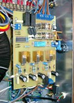
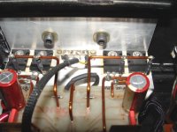
Hi Borc, I will be using the exact same gold heatsinks for my MJE15030 and MJE15031. The only problem I have is that the transistor leads are extremely close to the heatsink (at the point where they bend and go into the pcb.
Is there any specific reason why you mount the transistor flat on the board? I will most probably solder mine as it is (upright) and then just put the heatsink onto it standing up.
Is there any specific reason why you mount the transistor flat on the board? I will most probably solder mine as it is (upright) and then just put the heatsink onto it standing up.
I made heatsinks from Zalman fan regulator switch for computers(FanMate or something, three position with regular diodes in series for voltage drop ).
The color was right for Audio (gold") ) Cut them on half and this is perfect match for Leach. With mounting flat on the board made the construction(transistor+heatsink) more stable.
) Cut them on half and this is perfect match for Leach. With mounting flat on the board made the construction(transistor+heatsink) more stable.
The color was right for Audio (gold
) Cut them on half and this is perfect match for Leach. With mounting flat on the board made the construction(transistor+heatsink) more stable.


 Greetings
Here is a gallery of my first leach amp:
http://www.briangt.com/gallery/leachamp-2channel
(my first diy project, a little over 2 years ago)
and one I helped a friend build:
http://www.briangt.com/gallery/jeetamp
(I cut the metal, then showed him how to put it together)
and a chassis I made for another friend for a 5-channel leach amp:
http://www.briangt.com/gallery/leachamp-5channel
(internal pictures on his website, can't find the URL at the moment)
--
Brian
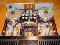
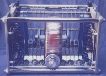
Here's another one built into an old transmitter output tuning cap.
By the way; pcbs, and schematics in protel format for both the Super amp and the 4.5 amp are here--> www.sidesign.co.nz
By the way; pcbs, and schematics in protel format for both the Super amp and the 4.5 amp are here--> www.sidesign.co.nz
Attachments
Pics of my Leach Amp. http://www.geocities.com/jojod818/leach_amp/leach_low_tim.htm
- Status
- This old topic is closed. If you want to reopen this topic, contact a moderator using the "Report Post" button.
- Home
- Amplifiers
- Solid State
- post your leach amp photos