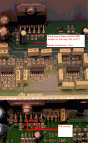
Hi ALL-
I was hoping some one could tell me if R6 or R7 was the negative feedback resistor for this amp.
Any assistance would be greatly appreciated.
Sorry for the zipped file, but my picture was to big to display here.. If anyone knows how to shrink a picture I would appreciate that info too.
Thanks in advance,
Troy
Attachments
sreten- Thank you very much for posting the picture and yes I need to increase gain of tweeter circuit to match the woofer circuit gain.
All- I am sorry for the lack of description, It just occured to me that you can't read my mind.
The two boards in the picture are both Alesis amplifiers from their powered speaker line.
The top one is a complete unit consisting of a pwr sply, amp circuits, and mounting plate which reads Alesis M1 Active.
The lower one is just an amp module with X-over. I bought both units from Steve @ Apex.jr but he didn't have any details on the larger complete unit.
The smaller bottom unit in the picture has the complete schematic and parts break down so I am possitive hat R3 is the NFB resistor for that amp.
I was hoping some one was familliar with the top completed model and could identify the correct resistor to adjust NFB there also.
Thanks again for any assistance.
Troy
There are usually two negative feedback resistors, changing
either will change the gain as gain is dependant on the ratio.
Usually to increase gain you would increase the larger value.
The larger value will be connected directly to the output one
end and the other resistor and input the other end, should be
easy to trace.
 sreten.
either will change the gain as gain is dependant on the ratio.
Usually to increase gain you would increase the larger value.
The larger value will be connected directly to the output one
end and the other resistor and input the other end, should be
easy to trace.
Hi sreten-
Agreed on changing the value of the larger resistor.
Here is the schematic for the lower amp in the picture.
http://www.apexjr.com/images/alesis_amp.pdf
R3 is to be moved from a 10K to an 18K resistor.
I was just hoping someone with the same knowledge of the smaller first amp would also have knowledge of the second.
Thank you for your time and effort.
Would anyone know how to move a thread? I think this thread would be better seen in Electronics and parts.
As always, thanks for your time,
Troy
- Status
- This old topic is closed. If you want to reopen this topic, contact a moderator using the "Report Post" button.
- Home
- Amplifiers
- Solid State
- Changing the NFB resistor to balance gain.
