I'm trying to make a simple delayed on circuit for my headphone amp to prevent power-on thumps. RainerB on the headwize forums pointed me to the eaton amp which has the following slow-on circuit:
After much frustration about the relay not comming on i did a little testing, but before that i'll just say what is different:
1. The pot is 200kohm not 250k (right pin on +ve and wiper connected to the transistor base, the left pin touches nothing!)
2. i'm trying to power it from 12v not 24
3. i'm using a 2n2222A transistor not a 2n2222.
4. my capacitor is 470uf 16V not 35V
Basically after much frustration about nothing happening on the output i measured the voltage accross the capacitor. This rises steadily like it should at about 0.15v / second, however that's when there is no transistor in the circuit. As soon as the transistor is placed in the circuit the capacitor begins to behave differently. It charges at the same rate but stops charging at 0.6v. It does this regardless of if the output is conected or not, it never sets of the transistor, and therefor never the relay. Different capacitor values and resistor values do nothing. I've tried the transistor around both ways to make sure it was connected right, but it behaves the same no matter what happens.
I've only used transistors twice so far so i'm not sure if something is wrong can anybody give a bit of insite?
An externally hosted image should be here but it was not working when we last tested it.
After much frustration about the relay not comming on i did a little testing, but before that i'll just say what is different:
1. The pot is 200kohm not 250k (right pin on +ve and wiper connected to the transistor base, the left pin touches nothing!)
2. i'm trying to power it from 12v not 24
3. i'm using a 2n2222A transistor not a 2n2222.
4. my capacitor is 470uf 16V not 35V
Basically after much frustration about nothing happening on the output i measured the voltage accross the capacitor. This rises steadily like it should at about 0.15v / second, however that's when there is no transistor in the circuit. As soon as the transistor is placed in the circuit the capacitor begins to behave differently. It charges at the same rate but stops charging at 0.6v. It does this regardless of if the output is conected or not, it never sets of the transistor, and therefor never the relay. Different capacitor values and resistor values do nothing. I've tried the transistor around both ways to make sure it was connected right, but it behaves the same no matter what happens.
I've only used transistors twice so far so i'm not sure if something is wrong can anybody give a bit of insite?
Garbz said:As soon as the transistor is placed in the circuit the capacitor begins to behave differently. It charges at the same rate but stops charging at 0.6v.
of course it will stop at 0.6v (Vbe for a silicon transistor),
") .
.the said circuit will not work because of that.
What you can do, however, is to place a resistor at the base of the transistor so it "isolates" the be junction of the transistor from the R/C charging portion of the circuit.
I don't see a protection diode. (This should be a diode across the relay pointing towards V+) You may have already destroyed your first transistor, check it if you can.
P.S. When using a pot as a variable resistor one usually connects the "free" side to the center. This is to avoid going open-circuit during adjustment.
P.S. When using a pot as a variable resistor one usually connects the "free" side to the center. This is to avoid going open-circuit during adjustment.
That's all it can charge to, seeing as how it's connected from the base to the emitterAs soon as the transistor is placed in the circuit the capacitor begins to behave differently. It charges at the same rate but stops charging at 0.6v.
Do you have some sort of resistor in series with the coil? Is it to large? Is your coil a 12V coil? What is the C-E voltage after the cap charges up? If it's below about 200mV, then the transistor has done all it can do and the problem is not enough current to trip the relay.
wow thanks for the speedy replies. I'm not used to this, on other forums a simple question can take days.
I've figured out hte problem it's because of the voltage drop across the transistor. I was using a 12v relay, and no I didn't destroy the transistors, and i always did use a protection diode. This schematic isn't mine.
The transistor did acutaly work, but only forwarded 4.7v out of the 9.8v input it got. This was definatly not enough to throw it. The solution was a second transistor another 2n2222 connected.... not in parallel... but... basically emitter of one to the base of the other, and bind the two collectors together.
The end result other than a 2 second increase in time it took since the capacitor needed to reach 1.2v, the forwarded voltage was about 9.5v which was enough to trip the relay.
Thanks a lot for all the responses. My guess is that the original schematic at the top used a 12v relay on the 24v rails. A secont transistor was MUCH cheaper then buying another 5v relay:
I've figured out hte problem it's because of the voltage drop across the transistor. I was using a 12v relay, and no I didn't destroy the transistors, and i always did use a protection diode. This schematic isn't mine.
The transistor did acutaly work, but only forwarded 4.7v out of the 9.8v input it got. This was definatly not enough to throw it. The solution was a second transistor another 2n2222 connected.... not in parallel... but... basically emitter of one to the base of the other, and bind the two collectors together.
The end result other than a 2 second increase in time it took since the capacitor needed to reach 1.2v, the forwarded voltage was about 9.5v which was enough to trip the relay.
Thanks a lot for all the responses. My guess is that the original schematic at the top used a 12v relay on the 24v rails. A secont transistor was MUCH cheaper then buying another 5v relay
:Called a Darlington.The solution was a second transistor another 2n2222 connected.... not in parallel... but... basically emitter of one to the base of the other, and bind the two collectors together.
Your original transistor just didn't have enough gain to do the job.
Garbz said:Basically after much frustration about nothing happening on the output i measured the voltage accross the capacitor. This rises steadily like it should at about 0.15v / second, however that's when there is no transistor in the circuit. As soon as the transistor is placed in the circuit the capacitor begins to behave differently. It charges at the same rate but stops charging at 0.6v.
[/B]
That's when the BE diode of the transistor starts conducting. It then eats all the charging current away. The current gain of the transistor may not be enough to switch it completely ON.
6 times the capacitance and 1/6th the resistance will probably work better.
Or use a Darlington transistor. This can be constructed from 2 Transistors. Google for the connection, it's standard. The Darlington switches at 2 * 600 mV, so you have to adjust the delay.
A small N-MOSFET fits the bill, too. But then you have to limit the gate - GND voltage to something like 6V because otherwise the capacitor would charge all the way to 24V, not good for your 16V cap nor for the gate of the MOSFET.
Somebody already mentioned the diode across the relay coil. If the relay switches OFF, the stored energy in the coil is transformed into a voltage spike that easily may kill the 2N2222. The diode offers a less destructive path for the spike. 1N4148 or 1n4001..4007 will do.
regards, Gerhard
Garbz, you forgot a couple of things.
1 Calculate necessary base current, then you know the max potentiometer resistance.
2 Capacitor value. Remember that the cap will not get charged to supplyvoltage, only 0.6-0.7 votls and this will make a shorter charge time than usual.
3 Diode across the base resistor in order to discharge the cap.
4 Diode across the relay coil in order to protect the transistor.
As inspiration you could check out my soft start. My goal there was to make a very short discharge time.
http://home.swipnet.se/~w-50719/hifi/sst01
A really good tool is in fact to simulate. Download LTSpice from www.linear.com and do some breadboarding in the computer.
for that kind of circuits, I always use a zener between the cap and the transistor base. That way, the cap can charge up to zener voltage + vbe drop. You can use a lower value cap and a smaller resistor that supply enough current to the transistor base.
at power down, the relay falls almost immediatly because the zener stops conducting.
here's the schematic. The interesting part is on the right
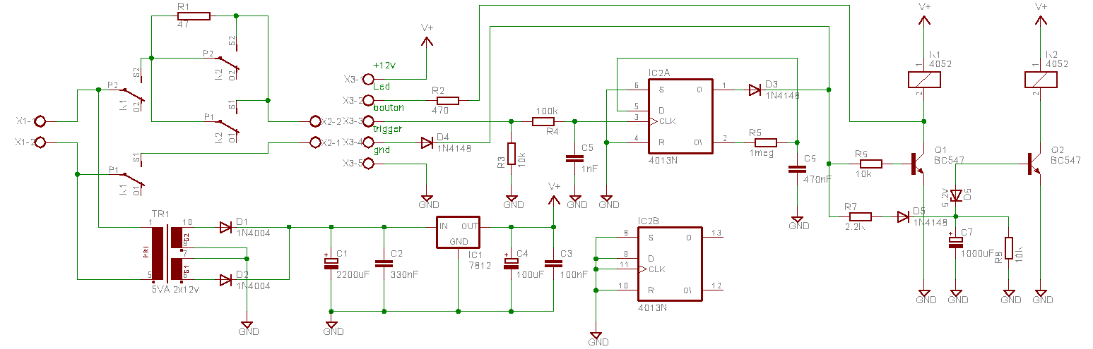
at power down, the relay falls almost immediatly because the zener stops conducting.
here's the schematic. The interesting part is on the right
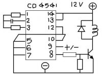
Here is the ckt using 4541. U need not worry about power-on reset as it is buit in.
For details, google CD4541. They are easier than designing the transistorised timer and is versatile. Only see that u put a small filter cap after a separate half wave diode rect so that it goes off fast on dc failure. Good for de-thump.
Also good for slow oscillations/pulses
The resistor at pin 1 could be a series connected combination of resistor and a preset for adjusting the time.
Gajanan
Attachments

- Status
- This old topic is closed. If you want to reopen this topic, contact a moderator using the "Report Post" button.
- Home
- Amplifiers
- Solid State
- Problem with really simple circuit!