watching the scheme it appears at least another 5 small caps should be damaged because of that mistake
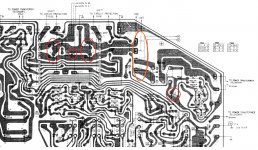
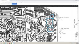
If you follow the schematic (print that section of the page and use a highlighter) - start from the 28v transformer marked "ORG" at the top, just looking at the positive phase of the AC signal:
ORG : Junction 303 : Relay Pin 12-4 : Junction 343 : Junction 64 : Conducting through top LH SUPA2100 Diode : Junction 61 : Through reversed C3 : GND.
Once the reversed C3 broke down internally and became conducting, there would have been very little resistance between AC28 : Rectifier Diode : Ground (i.e very high current until the rectifier died / fuse blew).
The point at the relay pin 12 : D511 is now pulled down to almost ground potential so there will be little or no current through D511. Anything past D511 should not have had a current load / should not have been damaged.
\\\\\\\\\\
Did you check that your transformer is outputting 28VAC?
Do you get +/- 37.5v after the rectification stage?
Do you have DC on your speaker outputs?
Have you made sure there are no other problems caused when you changed the other caps? Any solder bridges? Any other components mis-oriented?
The only person that can determine whether a component is damaged and needs changing is you. If you logically suspect a faulty component, remove it and test it. If it is ok, put it back, tick it on the schematic and move on to the next logical point.
Changing components without confirming serviceability first is an expensive method of repair.
Thank you for your help .If you follow the schematic (print that section of the page and use a highlighter) - start from the 28v transformer marked "ORG" at the top, just looking at the positive phase of the AC signal:
ORG : Junction 303 : Relay Pin 12-4 : Junction 343 : Junction 64 : Conducting through top LH SUPA2100 Diode : Junction 61 : Through reversed C3 : GND.
Once the reversed C3 broke down internally and became conducting, there would have been very little resistance between AC28 : Rectifier Diode : Ground (i.e very high current until the rectifier died / fuse blew).
The point at the relay pin 12 : D511 is now pulled down to almost ground potential so there will be little or no current through D511. Anything past D511 should not have had a current load / should not have been damaged.
\\\\\\\\\\
Did you check that your transformer is outputting 28VAC?
Do you get +/- 37.5v after the rectification stage?
Do you have DC on your speaker outputs?
Have you made sure there are no other problems caused when you changed the other caps? Any solder bridges? Any other components mis-oriented?
The only person that can determine whether a component is damaged and needs changing is you. If you logically suspect a faulty component, remove it and test it. If it is ok, put it back, tick it on the schematic and move on to the next logical point.
Changing components without confirming serviceability first is an expensive method of repair.
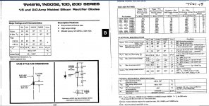
The D511 appears to be a 600v 1A diode ( the old 10d1).
I will replace that .
Now when I power the amp the relay is connecting the same time without any delay and there is a boom sounds in the speakers .
There is music in only one speaker but the signal is very distorted and thin.
Regarding the power amp by reversing the polarity means that 10-9 8-7 have been reversed inside the power amp board .
This traces are connected to the main power transistors TR409 +37V TR410 -37V that was reversed when I reversed polarity .
Attachments
On google D511 appears to be a 600v 1A diode but watching the specs of RVD10D1 I'm not so sure with what to replace . I can't find the original. What should I use instead ?. I uploaded the original specs of 10D1.If you follow the schematic (print that section of the page and use a highlighter) - start from the 28v transformer marked "ORG" at the top, just looking at the positive phase of the AC signal:
ORG : Junction 303 : Relay Pin 12-4 : Junction 343 : Junction 64 : Conducting through top LH SUPA2100 Diode : Junction 61 : Through reversed C3 : GND.
Once the reversed C3 broke down internally and became conducting, there would have been very little resistance between AC28 : Rectifier Diode : Ground (i.e very high current until the rectifier died / fuse blew).
The point at the relay pin 12 : D511 is now pulled down to almost ground potential so there will be little or no current through D511. Anything past D511 should not have had a current load / should not have been damaged.
\\\\\\\\\\
Did you check that your transformer is outputting 28VAC?
Do you get +/- 37.5v after the rectification stage?
Do you have DC on your speaker outputs?
Have you made sure there are no other problems caused when you changed the other caps? Any solder bridges? Any other components mis-oriented?
The only person that can determine whether a component is damaged and needs changing is you. If you logically suspect a faulty component, remove it and test it. If it is ok, put it back, tick it on the schematic and move on to the next logical point.
Changing components without confirming serviceability first is an expensive method of repair.
Also I;m planing to replace a few zener diodes (d508 and 509) and transistors 601,602,603
Attachments
Last edited:
,My transistor meter is broke so I can\'t check so this is more a blind repair by replacind all the suspects by fallowing the scheme without checkingIf you follow the schematic (print that section of the page and use a highlighter) - start from the 28v transformer marked "ORG" at the top, just looking at the positive phase of the AC signal:
ORG : Junction 303 : Relay Pin 12-4 : Junction 343 : Junction 64 : Conducting through top LH SUPA2100 Diode : Junction 61 : Through reversed C3 : GND.
Once the reversed C3 broke down internally and became conducting, there would have been very little resistance between AC28 : Rectifier Diode : Ground (i.e very high current until the rectifier died / fuse blew).
The point at the relay pin 12 : D511 is now pulled down to almost ground potential so there will be little or no current through D511. Anything past D511 should not have had a current load / should not have been damaged.
\\\\\\\\\\
Did you check that your transformer is outputting 28VAC?
Do you get +/- 37.5v after the rectification stage?
Do you have DC on your speaker outputs?
Have you made sure there are no other problems caused when you changed the other caps? Any solder bridges? Any other components mis-oriented?
The only person that can determine whether a component is damaged and needs changing is you. If you logically suspect a faulty component, remove it and test it. If it is ok, put it back, tick it on the schematic and move on to the next logical point.
Changing components without confirming serviceability first is an expensive method of repair.
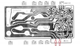
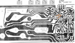
After replacing the main caps , the rectifier , the relay, I'm planing to replace
3 transistors and 3 diodes which a showed with red in this photo .
Is this enough if I replace all those components in order to restore the amp ?.
All caps are installed ok .
I just want to cure the reversed mistake by replacing all the suspected components .
I presume that resistors are ok and the only problem is with transistores and diodes .
Do you think more transistors or diodes need replacement .
Thanks
Attachments
I started the mod and replaced all caps but I made a big mistake.
I installed the two main 10000uf filter caps backwards .
I installed the 342 amp negative blue wire to the positive side the cap and the 341 amp red positive wire to the negative side of the second cap.
I blew the 2A fuse .and more damage was done
How can I fix this ? What should I expect ?
Thanks
If your that dangerous I would get a pro to fix it.
You might cause even further problems if you get it wrong again or worse kill yourself.
I used to be pretty dangerous around HV and got quite a few shocks as a lad.
These days with the benefit of experience I don't get it wrong too often.
With electronics you have to go slow and carefully. When I build my own amps I check each component at least twice for correct position on the pcb and twice for the correct value.
The rectifiers might be toast if the caps were the wrong way around. I would certainly replace the big caps.
Who knows what other damage connecting up the other cap wrong did.
It probably destroyed any semiconductors connected to that part of the circuit.
Either get a pro to fix it or bin it and buy in another but this time take much more care.
I replaced all 3 transistor and the diode around relay and the relay with a new one but still the relay is connecting with 0 delay and the amp is sending a shock to speakers .
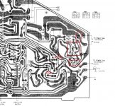
So I replaced TR 601,602,603 and diode D511, I also uploaded a photo .
I don't understand why the relay is not fixed .
So I replaced TR 601,602,603 and diode D511, I also uploaded a photo .
I don't understand why the relay is not fixed .
Attachments
I was hoping to repair this my self . I measured different transistors with the multimeter and they are working fine . Maybe I need a better measuring device to see if they are really ok ?. Also I checked all diodes and are all fine .Where do you live? I cant see you ever getting this repaired with your lack of training or experience. Maybe you can find a member or local audio guy with the experience.
If your in N fla, i could help you.

I can;t reach you . If I find a local tech who knows how long the amp will last ?.
I know there are some good technicians but some will improvise and the amp won't last ..
I will start learning and in 1 or 2 years I will repair every amp
Right now I was hoping for a quick fix thinking that by fallowing the traces and checking the components will fix the amp
I have been reading this thread and Tbh, find it hilarious.
OP: if you are serious about repairing this Amp, then please "diagnose" the fault and then "fix". It is highly unlikely that you will stumble upon a working set of components soldered in place - that's not how repair works. Repair is following a logical set steps - observe, think, deduce, check, replace/fix and test, sometimes iteratively.
And do note that sequentially replacing components, turning it on to check, then replacing some more is also unlikely to work, because you may have already blown something you replaced the first time around.
Good luck.
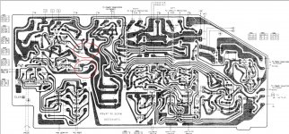
Yesterday I managed to fix the relay issue . Now is clicking on after 3 seconds the amp starts . The problem was with tr408 which was completely shorted . Showed on photoI have been reading this thread and Tbh, find it hilarious.
OP: if you are serious about repairing this Amp, then please "diagnose" the fault and then "fix". It is highly unlikely that you will stumble upon a working set of components soldered in place - that's not how repair works. Repair is following a logical set steps - observe, think, deduce, check, replace/fix and test, sometimes iteratively.
And do note that sequentially replacing components, turning it on to check, then replacing some more is also unlikely to work, because you may have already blown something you replaced the first time around.
Good luck.
I tested all other transistors and the hFE is under 200 for all and there is no short also I tested all diodes and they are all good .
There is a strange problem with 2 high woltage transistors tr506 tr501 (showed on photo).
If I test those tr506 tr501out of circuit they are fine but once mounted in circuit there is a short between emiter and conductor but only in one direction (showing around 1600 on diode probe). If I reverse the multimeter probes there is no short on that E-C path.
Is this normal ?what is causing this ?.
Also I measured the transformer impedance right from the cable and it shows 9 ohms .
Now the amp is almost solved but still there are some bad parts that need to be replaced .
Should I also start testing some resistors and ceramic caps ???.
What other parts are susceptible of failure because of reverse voltage ??
Now in one speaker there is a very distorted sound and the other no sound .
Thanks
Attachments
I started digging and found over 20 resistors shorted they act live wires WTF is this ? You guys told me that is not so serious !.
At the beginning of this thread some mentioned that only the rectifier, and some transistors and the relay need to be replaced but they are all ok .
Contrary over 20 resistors are shorted
So it seems I need to take this more serious which is a nightmare because I don't have time !
Was hopping for a quick fix !
Intead of offering some accurate advices you are macking fun ?
I bet that some of you knew about resistors by watching the scheme
Last edited:
Persecution complex much ?
I bet your testing the resistors in circuit.
If you are.
Then I suggest you go away, stop abusing those trying to help you, and learn some very basic electronics.
The very first, most basic, and second most valuable tool at you disposal is a multimeter.
As you obviously don't understand how to use one properly, you have no hope of fixing anything more complex than a lawnmower.
Those here trying to help you are those that have spent many years training, many more decades repairing, and have forgotten more than you (and I) will ever hope to learn.
They've tried walking you through testing things, yet you ignore them then abuse them.
 infraction meted out, thread closed...
- Status
- Not open for further replies.
- Home
- Amplifiers
- Solid State
- I damaged my Technics SU-3500 amp