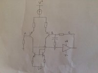
Friends, I need your help. I built a power amp circuit on a breadboard (and some perfboard and heatsink) and I have been trying to measure DC offset and other operating voltages. But my readings don't make any sense. I've attached a diagram of the circuit I am testing. I am trying to take voltage readings at three points relative to ground V(A), V(B), V(C), and the relative voltage V(B,C) where I would expect V(B) = V(B,C) + V(C), but read on!
I am powering my circuit with a bench power supply outputting +35V, 0V, -35V and have set a current limit of 500mA per rail. The nominal current draw of the circuit is around 150mA per rail. I shall call the supply current per rail "Is".
I have a Fluke 175 multimeter that has a mVDC mode for voltages <600mV and an autorange VDC mode. I also have a cheap CEN-TECH multimeter with a setting for low voltages (mV range).
Before I continue, let me show the measurements I took.
Firstly I wasn't expecting my voltage measurements to have such a dramatic effect on the supply currents. These multimeters have >10M input impedance and should draw negligible current. In the first Fluke VDC the current is so high it hits the limit I set. Why would this happen? I mean, if there was some stray parasitic from the probe that was causing instability, why would this only occur on the VDC setting and not on the mVDC setting? In other cases (V(B) & V(B,C)) the current drops substantially from its nominal value.
Second, the V(C) reading for Fluke mVDC is way off the corresponding VDC and CT readings and looks suspiciously like a diode/base-emitter forward voltage. What the **** is going on there?
Third, why is Kirchoff's law not obeyed in any of the cases?
I am powering my circuit with a bench power supply outputting +35V, 0V, -35V and have set a current limit of 500mA per rail. The nominal current draw of the circuit is around 150mA per rail. I shall call the supply current per rail "Is".
I have a Fluke 175 multimeter that has a mVDC mode for voltages <600mV and an autorange VDC mode. I also have a cheap CEN-TECH multimeter with a setting for low voltages (mV range).
Before I continue, let me show the measurements I took.
Code:
           Fluke VDC      |   Fluke mVDC    |   CT mV
--------------------------------------------------------------------
[B]V(A),Is[/B]:   118mV,>500mA!  |   122mV,140mA   |   114mV,125mA
[B]V(B),Is[/B]:   105mV,90mA     |   116mV,90mA    |   150mV,115mA
[B]V(C),Is[/B]:   150mV,145mA    |   650mV,145mA   |   131mV,145mA
[B]V(B,C),Is[/B]: 85mV,85mA      |   93mV,65mA     |   76mV,105mA
Firstly I wasn't expecting my voltage measurements to have such a dramatic effect on the supply currents. These multimeters have >10M input impedance and should draw negligible current. In the first Fluke VDC the current is so high it hits the limit I set. Why would this happen? I mean, if there was some stray parasitic from the probe that was causing instability, why would this only occur on the VDC setting and not on the mVDC setting? In other cases (V(B) & V(B,C)) the current drops substantially from its nominal value.
Second, the V(C) reading for Fluke mVDC is way off the corresponding VDC and CT readings and looks suspiciously like a diode/base-emitter forward voltage. What the **** is going on there?
Third, why is Kirchoff's law not obeyed in any of the cases?
Attachments
Last edited:
When DC bias measurements make no sense at all, it is often due to oscillations. Could you try soldering 10 kohm resistors to the nodes under test and measuring at the other side of the resistor, so whatever capacitance the meter and wires have won't be directly connected to the circuit?
Do you see hand effect, DC voltage readings that change when you just point at a sensitive node somewhere? With +/- 35 V you can still safely check for that, as long as you make sure not to touch two nodes simultaneously.
Do you see hand effect, DC voltage readings that change when you just point at a sensitive node somewhere? With +/- 35 V you can still safely check for that, as long as you make sure not to touch two nodes simultaneously.
Last edited:
No it's a discrete power amp, I just simplified the diagram.I am assuming that's an IC power amp on the output , if so its negative input needs to be connected to the other collector of the long tail pair and you will probably need a low value capacitor across the feedback resistor connecting B and C .
Too late to add to my above post..................
Agree with " MarcelvdG" the circuit is oscillating .If you have not included an IC power amp then you need to show a lot more of the circuit as frequency compensation would normally be applied around the circuit details you may have omitted .
Agree with " MarcelvdG" the circuit is oscillating .If you have not included an IC power amp then you need to show a lot more of the circuit as frequency compensation would normally be applied around the circuit details you may have omitted .
Could you try soldering 10 kohm resistors to the nodes under test and measuring at the other side of the resistor, so whatever capacitance the meter and wires have won't be directly connected to the circuit?
This improves things a bit. The Is supply current reading goes up to 200mA per rail and doesn't hit the ceiling for the Fluke V(A) VDC reading. And the weird 650mV reading at V(C) disappears - its just in line with the other readings.
Do you see hand effect, DC voltage readings that change when you just point at a sensitive node somewhere?
No, I don't see this happening.
I'll confirm oscillations with my oscilloscope and report back.
EDIT: My oscilloscope is not working. It may take me a while to get some readings.
Last edited:
Agree with " MarcelvdG" the circuit is oscillating .If you have not included an IC power amp then you need to show a lot more of the circuit as frequency compensation would normally be applied around the circuit details you may have omitted .
Here is the full circuit I have built. According to my Spice simulations:
26dB negative feedback @20kHz
Gain Crossover Frequency: 375kHz
Phase margin: 80 deg
Gain margin: 22dB
The mixed mode feedback configuration raises the output impedance to around 2ohm - good for a guitar amp.
Attachments

I'll confirm oscillations with my oscilloscope and report back.
EDIT: My oscilloscope is not working. It may take me a while to get some readings.
There are three types of oscillations to worry about:
1. Oscillations related to a lack of small-signal stability of the overall loop.
2. Large-signal oscillations of the overall loop.
3. Oscillations related to wiring parasitics.
You have analysed type 1 by simulating gain and phase margins, so assuming you did that correctly, this type of oscillation is unlikely.
You can more or less check for type 2 in simulations by transient simulating power-on transients and hard clipping and checking that the amplifier always recovers properly.
Type 3 is not covered at all by simulations unless you include models for all wiring. Base, gate or grid stopper resistors are meant to solve these oscillations by reducing the quality factor of the wiring, local supply decoupling by shorting supply wire inductance at high frequencies.
The oscillation frequency for type 1 and type 2 oscillations is usually a few megahertz or less, type 3 can occur at hundreds of megahertz, up to the fmax of the transistors. That is, you need a fast scope to see anything. With my 150 MHz analogue scope I can see 200 MHz to 300 MHz oscillations, but with the 20 MHz scope I used to have, I didn't see them at all.
Last edited:
Try putting 100 ohms in series with the bases of Q22 and Q23 (base stopper resistors).
Yes I will try base stoppers. Thanks.
The oscillation frequency for type 1 and type 2 oscillations is usually a few megahertz or less, type 3 can occur at hundreds of megahertz, up to the fmax of the transistors. That is, you need a fast scope to see anything. With my 150 MHz analogue scope I can see 200 MHz to 300 MHz oscillations, but with the 20 MHz scope I used to have, I didn't see them at all.
I have a 300 MHz DSO but it has stopped working (it's a "cheap" one so I guess it was a risky buy, but luckily it is still under warranty so I'm getting a refund). I'm get another next week and hopefully I'll see something.
Isn't Q10 and Q11 OFF?
No, definitely not.
80 degrees of phase margin is not a good design practice.
Really? How big of a margin do you consider good practice?
The first thing to do is get a working scope. You can then check whether the amplifier is oscillating at all and if it does, the oscillation frequency will give you an idea whether it is the whole loop that oscillates or some local wiring-parasitics-related issue. In the latter case, you can connect the ground lead to the probe tip, use the probe as a magnetic loop antenna and move it around to see where the RF magnetic field is at its strongest. That will then hopefully indicate which part of the circuit oscillates.
- Status
- This old topic is closed. If you want to reopen this topic, contact a moderator using the "Report Post" button.
- Home
- Amplifiers
- Solid State
- Help with probing a power amp circuit