Please do not misunderstood!
Read all and them have your conclusions.... and please, tell me what you think...no problems to say "awfull".... "uggly".... "stupid".... "fool"... "interesting".... "i Like it".... "crazy.... everything can be done...but think about that SMD assembling has some similarities in the way is concepted.
I am not saying that Printed Circuit Boards are Bad!... they are wonderfull!.....but some of them are so perfect that i have no courage enough to put solder on it....better to put in a frame in my rest room.
Mr Jan dupont....my expert "gurú" makes a very special material that you can see trought lenses and not fail can be seen... double faced, reliable, flexible, clear, clean, pretty and magnificent.... you can see it in his site:
www.audio-circuit.dk
He is sometimes with us in this forum..... but i think that kind of "state of the art" material is for serial use...not the way i done just to hear how some circuit "sounds".... and them try another.... so no need to perpetual assemblies..... also i cannot look inside because no glass cover on my equipments.... this way, ugly material is good enough to me.
Better to use good photografic printed circuit boards, with inscriptions on it... double faced.... etcetera, when you assemble something to perpetuate... to stay with you life long....not my case.
Where's the portuguese language people?...hey, appear and E Mail me!
Cadê a turma de lingua luza..... vamos sair detraz do tôco gente.... os gringos, por vezes, metem chumbo grosso.... é preciso que a gente mantenha o pé no pedaço.... êles acham que somos indios.... alguns de nós de fato somos....mas vamos lá!
This was a special message in portuguese to wake up my language brothers!
I will make answers to myself ... this way no frustrations...... once no one told me nothing...neither "fool"..... that's awfull!
Carlos is the Destroyer X
Attachments

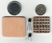
This one is the destroyer X
The picture you view show a board that was used many times, two years long using it.
The board was used to regulate power supply
Was used too as microfone compressor to ham transmissions
Was used as a beat oscilator
Was used as a power amplifier
Thats all i can remember because becaming old (52).... that's the reason is almost "destroyed" by use.
Here's my face looking at you..... trying to disturb and challenge your to came hear and face me!
Lets use the old way again.
YOU KNOW? THE REASON WHY YOU DO NOT LIKE IS BECAUSE YOU HAVE NO GOOD HANDS TO DO SUCH A THING.... YOUR HAND SHAKES (HAHAHAHA!)
Carlos
Attachments

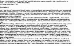
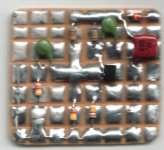
I assemble this one just to show you.
Believe that this is an amplifier.
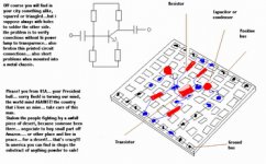
I know capacitors are in resistor places, also that the transistor is not adequated, also the leads inverted..... this is only a picture, made as flat as possible because have no digital photo machine....not web camera too....this way i use the scanner....transistor is not show vertical because focus deepness of scanner cannot work this way.... surface must be flat.
You can see solder flux that join some copper points.... you will see (bad focus) positive bar upside..... and negative bar downside.
I will put also a scratch of the circuit....notice that is very easy....just to assemble from left to rigth and mark in the schematics the parts already soldered.... also lines of interconection and jumpers must be color marked in schematics... to have sure you do not forget something, but this one do not need that, because is easy to make and check.
Take a look and you will understand..... yes, there are capacitors in resistor place...i know that.... was the small parts i found here at home.... consider the ones as resistors.... capacitors in the assembling is red and green.
Believe that this is an amplifier.
I know capacitors are in resistor places, also that the transistor is not adequated, also the leads inverted..... this is only a picture, made as flat as possible because have no digital photo machine....not web camera too....this way i use the scanner....transistor is not show vertical because focus deepness of scanner cannot work this way.... surface must be flat.
You can see solder flux that join some copper points.... you will see (bad focus) positive bar upside..... and negative bar downside.
I will put also a scratch of the circuit....notice that is very easy....just to assemble from left to rigth and mark in the schematics the parts already soldered.... also lines of interconection and jumpers must be color marked in schematics... to have sure you do not forget something, but this one do not need that, because is easy to make and check.
Take a look and you will understand..... yes, there are capacitors in resistor place...i know that.... was the small parts i found here at home.... consider the ones as resistors.... capacitors in the assembling is red and green.
Attachments
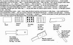
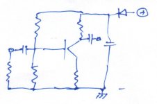
Here is the schematic used to make this assembling
This is an amplifier.... diode to not invert..... capacitor to avoid oscilations, to filter and stabilize..... colector resistor, emitter resistor.... an input resistor as a charge in the input.... two base resistors flowing 10 times expected Ib..... but do not have values, just because in the board i put component samples i had in house....only to show the "spatial" way of soldering....the circuit assembled do not works.....it is an image example... only that.
This is an amplifier.... diode to not invert..... capacitor to avoid oscilations, to filter and stabilize..... colector resistor, emitter resistor.... an input resistor as a charge in the input.... two base resistors flowing 10 times expected Ib..... but do not have values, just because in the board i put component samples i had in house....only to show the "spatial" way of soldering....the circuit assembled do not works.....it is an image example... only that.
Attachments
- Status
- This old topic is closed. If you want to reopen this topic, contact a moderator using the "Report Post" button.
- Home
- Amplifiers
- Solid State
- A New and Old circuit board, another way to assemble electronics