Hi,
Trying to design a low gain bipolar line amplifier stage and the first problem i find is that i get too much harmonic distorsion in the inputstage when i try to go from voltage to current.
The idea i had for the gain stage are dual current mirrors and then terminating the current in a resistor which determines the output impedance.
Any suggestions on a bipolar inputstage that has low distorsion.
Input impedance is not too critical 10k is fine.
Thanks
Mikael
Edit: The Subject was confusing so i changed it.
If you have some "what-if" questions, why don't you try LTSpice (freeware) and fool around with this program. LTSpice has also FFT.
I have simulated four projects and the result has been rather good.
The most interesting simulation was for my QRV-06 headphone amp
http://www.diyaudio.com/forums/showthread.php?s=&threadid=23241&highlight=
You can have the simulation files. Send me a message.
If you want low gain and not the lowest noise possible, try to insert emitter resistors (at the input transistors), 47-220 ohms or something like that. You could also test cascodes. This is good for distortion also. Check the result with LTSpice.
Traderbam:
For the input stage or the whole line amp?
For the input stage since i would like to have it current out i suppose as high as possible but small enough to not cause distorsion due to the following (currentmirror) stages is fine.
Peranders:
Already running winspice simulations. The problem is that i cannot seem to get the THD down below 2% with my current input stage which is a stage based on as you suggested emitter resistors. Where i take the collector currents to the current mirrors. Tha problem i have is that almost all the distorsion seem to stem from the input stage.
I should note though that i have used 1k-10k emitter resistors but the distorsion didn't seem to go down if i went for the smaller values.
Another factor that might be limiting in my application is the low supply rail +-10 and the input swing of 1.5v AC.
Thanks for the replies.
hjelm,
Could you explain a little more about what you are trying to achieve?
It sounds to me like you are trying to make a line amp (voltage gain?) with 10k input Z (output Z?, max output V?).
You seem to be having trouble with the first stage linearity - but what is the second stage? Are you intending to use feedback or are you trying to make an open-loop design? Are you talking about having dual diff pairs feeding current mirrors then feeding a common resistor to ground?
For a diff pair stage the best linearity occurs when the differential current is very small compared with the bias current and the bias current with no signal is identical in each transistor.
In any case your best sound will be if you use a simple asymmetrical design, diff pair feeding CE with feedback.
Traderbam
The thing I am trying to achieve is a line amp with gain 2.
This is simple enough and I could probably find something on the net or in this forum, or use an opamp.
I would however like to create something by myself if possible, I would probably reinvent the wheel or at least an octagonal version of it in the process but it would be a learning experience.
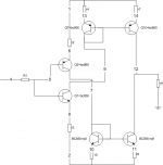
My plan was as you say to use a dual transistor input with emitter resistors, not differential, and two current mirrors and feed the current through a common resistor to ground. The idea was that the symmetry would remove some distorsion.
The design criteria were bipolar devices BC550C BC560C open loop class A.
This doesn’t seem to work and it seems that the emitter resistor idea is the one to blame.
Your last statement is interesting but I would like to have an open loop amplifier if possible.
I am attaching the first version of the line amp i thought could work.
The thing I am trying to achieve is a line amp with gain 2.
This is simple enough and I could probably find something on the net or in this forum, or use an opamp.
I would however like to create something by myself if possible, I would probably reinvent the wheel or at least an octagonal version of it in the process but it would be a learning experience.
My plan was as you say to use a dual transistor input with emitter resistors, not differential, and two current mirrors and feed the current through a common resistor to ground. The idea was that the symmetry would remove some distorsion.
The design criteria were bipolar devices BC550C BC560C open loop class A.
This doesn’t seem to work and it seems that the emitter resistor idea is the one to blame.
Your last statement is interesting but I would like to have an open loop amplifier if possible.
I am attaching the first version of the line amp i thought could work.
Attachments
Hjelm, you could try a current feedback topology, like my amp. Your circiut is starting to like a current feedback amp.
Download LTSpice and test because this software (or any other SPICE software) is excellent if you just want to test. If you want to know the gain the software is pretty accurate.
Download LTSpice and test because this software (or any other SPICE software) is excellent if you just want to test. If you want to know the gain the software is pretty accurate.
It is certainly possible but I'll suspect that you must use cascodes in the current mirrors.
You can check my diamond output stage, both in the QRV-06 and in the separate buffer QRV-05. I have tested this buffer with excellent freeware Rightmark Audio Analyzer. With my soundcard I could draw the conclusion that the distortion was below 0.008%
You can check my diamond output stage, both in the QRV-06 and in the separate buffer QRV-05. I have tested this buffer with excellent freeware Rightmark Audio Analyzer. With my soundcard I could draw the conclusion that the distortion was below 0.008%
Hjelm,
Ok, I see now. You don't mention the values of any of the resistors or the supply voltages.
Idea 1: Obviously the non-linearity comes from the transistors - so one way to make this more linear would be to make the resistors as large as possible. Can you use quite high supply voltages and large resistor values to minimize the contributions of Vbe non-linearities?
Yes, I agree that you need to look at how to mitigate Vbe/Ic non-linearity, or in other words linearize the transconductance. Using cascodes is another kettle of fish and I'd recommend treating these as a last resort or you'll make the system too complex too early. I don't know what output V swing you require but cascodes will only make things worse if you just need a 1vp-p or so.
Idea 2: how do you make a transistor circuit have very linear transconductance? One of the most proven ways is a long-tailed pair arrangement, fed with a current source and with a current mirror on the tails. Rather than trying to cancel distortions using a symmetrical differentiator, why not use a LTP which will give considerably more linear results? The output can either be taken directly off the tail via a capacitor or you can add a second LTP/current mirror stage for extra gain.
Idea 2: how do you make a transistor circuit have very linear transconductance? One of the most proven ways is a long-tailed pair arrangement, fed with a current source and with a current mirror on the tails. Rather than trying to cancel distortions using a symmetrical differentiator, why not use a LTP which will give considerably more linear results? The output can either be taken directly off the tail via a capacitor or you can add a second LTP/current mirror stage for extra gain.
Really appreciated!
I do not know what a long tailed pair looks like but i will soon find out.
I have given up on the Vbe unlinearities they are Ic related and i want Ic to change so it was doomed from the start.
Thanks for the tip on the long pair.
The cascodes does not seem to be too popular in the input stages either so i that was probably a dead end anyway, tried it and got some results but they seemed to be more problem than the actual benefit you received.
If i am to be a bit lazy do you have any example of a long tailed pair on the net or any example schematic i would greatly appreciate it, if not i fully understand (its my homework).
Thanks
Hjelm, you have approx three options as emitter loads.
1 Plain resistor (as you have chosen) = good
2 Current source, BJT, JFET = better
3 Current source with cascode = best
A very stiff current source will reduce distortion. This goes also for your current mirrors.
Cascodes are the salvation You should try it! The only disadvantage is loss of output voltage.
1 Plain resistor (as you have chosen) = good
2 Current source, BJT, JFET = better
3 Current source with cascode = best
A very stiff current source will reduce distortion. This goes also for your current mirrors.
Cascodes are the salvation
You should try it! The only disadvantage is loss of output voltage.Just trying to get the right thinking here.
If i use current sources on the input i get a fixed Vbe.
With the Vbe fixed and the current IC fixed i have to use a high ohmic next stage?
This would mean i could make decent buffer but how do i acheive gain?
As for cascodes i see the applicability to linearize the current gain but what if i want to do voltage to current gain, or am i just stupid?
OK, I see what you mean but is the main goal here to have zero feedback? What about a current feedback amp with gain of 2? Then you can involve a couple of highly linear circuits and ther is more: low current consumption (if you want his), extremely high speed (10-30 MHz!), extremly low distortion.
You are making an assumption that a circuit that is symmetrical about the power supplies will be more linear than an asymmetrical circuit. You are not alone in this...it is a very common belief. But is it correct?I have even considered a single ended version provided the distorsion is small enough
Eg: some people do deceive themselves by thinking that something that looks prettier on paper will sound better. As if nature favours symmetry. However, IMO electrons don't give a wet slap!
Well the reasoning was that if you could create a toplology that had an unlinearity one way a way to cancel it would be to invert the topology and double it so the errors cancel eachother.
I am aware of the fact that npn and pnp devices are very hard to match linearitywise and that simulations might deceive you in presenting false symmetri, where in reality the devices don't match.
To be honest i am looking into a single ended topology right now but i am not understanding what i am doing so it's slow work. I get no gain in the circuit.
- Status
- This old topic is closed. If you want to reopen this topic, contact a moderator using the "Report Post" button.
- Home
- Amplifiers
- Solid State
- Symmetrical input stage