hi there
I've just completed a dual mono leach amp, 750VA trans with separate bridge and 10000uf caps per channel. It sounds fantastic. I've been building it for ages and it seems tip top, BUT...
I was testing one channel with a 1khz sine wave input on a 8ohm dummy load and the resistor with the inductor wound around it started to smoke.
I removed power immediately, amp still 'works' and no fuses blew. What's up with that? I'm certain that I've assembled it correctly, both channels are biased at about 110ma and play audio perfectly into both 4 or 8 ohm loads.
Any help would be appreciated.
Gareth
I suspect this inductor is not needed anyway, but people always seem to put them in.
For many/most bipolar output stages, even the classic EF triple T circuit (much less a CFP output stage!) both an RC zobel and a series parallel RL network are necessary to assure stability with reactive loads, inductive and capacitive.
There are ways around it, but I'm not telling....
The inductor does introduce frequency dependent load sensitivity, unfortunately- it often does have some kind of impact on HF sonics, depending on the speaker load. I wouldn't recommend removing the RL network from a standard Leach amp, unless you're just using it for subwoofer duties, for example.
The resistor in parllel is for damping the network; the inductor value will typically be in the range of 2-4 uH.
If you have a scope, you can determine the real problem pretty quickly.
It's brave souls who build and test amplifiers without a scope..

Best regards,
Jon
JonMarsh said:
For many/most bipolar output stages, even the classic EF triple T circuit (much less a CFP output stage!) both an RC zobel and a series parallel RL network are necessary to assure stability with reactive loads, inductive and capacitive.
Jon
I am familiar with all the arguements for using the damped inductor to buffer capacitive loads. Most of the expert opinion says it is de riguer, with one notable exception (Pass). I realize suggesting it it not necessary is heretical.
The Leach amp uses feedforward compensation, from driver to inverting input. Furthermore, it has a low-pass filter on the output feedback, which makes it even more immune to hf instability with capacitive loads. In my experience with similar amps, if properly applied those two techniques keep an amp stable into capacitive loads.
Nelson Pass pointed out that the inductor degrades the damping factor at higher frequencies, and so in fact can impact tweeter damping. In light of that, I'd at least experiment with leaving it out.
The thing here is that all the power should go through the inductor which should be quite large to avoid troubles. You may even solder the resistor underneath the PCB, it only provides oscillation dampening for the coil.
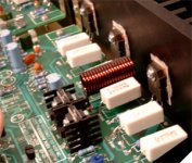
Bullet-proof sized inductor compared to the white 5W resistors:
Bullet-proof sized inductor compared to the white 5W resistors:
Attachments
As always, nice work
I always wanted to ask if you have a more detailed description on the wire connectors used - eg mm for wire diameter, cost, a link for an online shop where one can buy them. I hate those screw-type ones, they cause lots problems if you use them 'frequently'.
I always wanted to ask if you have a more detailed description on the wire connectors used - eg mm for wire diameter, cost, a link for an online shop where one can buy them. I hate those screw-type ones, they cause lots problems if you use them 'frequently'.
The connectors (in my picture) is Wago, german Spitzenklasselucpes said:As always, nice work
I always wanted to ask if you have a more detailed description on the wire connectors used - eg mm for wire diameter, cost, a link for an online shop where one can buy them. I hate those screw-type ones, they cause lots problems if you use them 'frequently'.
 connectors but since the patent expired all the other big elephants in the connector business have got similar products but nothing is like the original.
www.wago.com
Did you know, Wago changes the sound to a more unconstipated sound. In fact Wago does more for the sound than Black Gate caps. The reason for this is the sharp spring which makes the sound very tight, in fact air tight
..... no.... but they are good. So good that they are used on ships, trains and also burried in the railways (tough enviroment and heavy vibrations).peranders said:
Did you know, Wago changes the sound to a more unconstipated sound. In fact Wago does more for the sound than Black Gate caps. The reason for this is the sharp spring which makes the sound very tight, in fact air tight
Thanks, these might free my amps from soldering power rails directly to PCB
... Now... errr... where to buy less than 420 connectors? 
The Leach amp uses feedforward compensation, from driver to inverting input. Furthermore, it has a low-pass filter on the output feedback, which makes it even more immune to hf instability with capacitive loads. In my experience with similar amps, if properly applied those two techniques keep an amp stable into capacitive loads.
Both the loop topology, the output stage configuration, and the actual wiring/layout dress seem to influence the stability- including factors of loop or local oscillation. For a Leach circuit the "safe"way to go without "qualifying" it under specific load conditions for the actual unit construction is to retain the inductor.
That said, I haven't built an amp requiring an output inductor in over ten years; I agree with you that the effect is deletrious to the output impedance and creates opportunities for audible interaction with speaker loads, and in general seems to reduce HF resolution. In many cases, better safe than sorry, though.
Best regards,
Jon
- Status
- This old topic is closed. If you want to reopen this topic, contact a moderator using the "Report Post" button.
- Home
- Amplifiers
- Solid State
- leach amp inductor smoking