I dislike to waste power or headroom so I am interested in rail-to-rail output for audio amps.
An obvious idea is to look at what the IC industry have done on similar motivations.
The Monticelli output circuit looks clever and is widely used.
I suspect there may be a few tricks and traps once it's off an IC, Vbe match with temperature and the like.
A search of DIY finds little analysis but some mentions by people who should know, like Scott Wurcer and a few other experts.
It's also mentioned in "Art of Electronics" 3rd ed. but the details and simulations are promised in the as-yet-unreleased X chapters.
Anyone care to share their expertise so I know what to watch for in LTspice simulations?
Or, even better, share their LTSpice ASC too?
David
One thing to watch out for is the variation of active device capacitance (Cgd, Cgs, Cds, Cbe, Cbe, Cce) with voltage, when the output is near the rail. These capacitances are very carefully measured and modeled in an IC process, by a team of experienced professionals, using million dollar test equipment. The measured capacitances are thoroughly modeled in the very advanced SPICE models like "BSIM3" which has several dozen adjustable parameters, for a close fit over a wide operating range.
Discrete transistors, on the other hand, have comparatively little published characterization data showing C-versus-V at the low voltage end, and the simulation models typically found floating around the internet, are of questionable provenance and dubious quality. Use the simulator to extract C-versus-V of a power transistor model in your possession right now; does the simulator's curves look anything remotely like what's in the datasheets or in the textbooks?
If your amplifier circuit's stability when operating near the rail is at all sensitive to device capacitance, I suggest making the C-versus-V measurements yourself, so you can trust them. Or, so you can't blame anyone else if they're wrong.
One thing to watch out for is the variation of active device capacitance...
Thank you, that's a useful point, capacitance at low Vce (or Vds) needs care to simulate accurately.
I have done a couple of VDMOS models with all the latest parameters to model capacitance.
I was able to match the datasheet at least, pretty well.
Toni "ASTX" reported that they were very close to measured results so that provides me with some confidence.
If your amplifier circuit's stability...near the rail is at all sensitive to device capacitance...
I am rather conservative on stability for just this reason, I have explicitly looked at how the PM and GM drop off as the output nears the rails for an EF OPS - it's almost scary.
So it will be educational to see how it behaves for the Monticelli + CE.
...measurements yourself, so you can trust them. Or, so you can't blame anyone else...
This is a very unfashionable idea, more on-trend to blame everyone else [1]
Best wishes
David
[1] I am tempted to provide evidence based references to support this.
A quick look at Australian, US or British politics for instance.
Last edited:
In IC design with +-5 Volt rails every Volt is important.
But in Audio Amplifiesr with +-50 Volt supply rails, it is not worth
the trouble.
And it is very difficult to top the high peak current capabilities of
emitter followers.
Rail to Rail output stages have the collector at the output and the collector
is inherently a high impedance point.
A lot of feedback is needed to get the output impedance down to < 0.5 Ohm.
If you are concerned with power efficiency a Class-D Amp may be a better option.
Last edited:
I dislike to waste power or headroom so I am interested in rail-to-rail output for audio amps.
You might want to search patents, which can be tedious because the titles often use misdirection to avoid being easily found. You might check under Roy(al) Gosser but I can't think of other names just now.
Some of these circuits rely on area ratioing and/or tight thermal contact to set bias and you would need to work around this.
Our DSL drivers did a pretty good job getting just under a volt at .5A on a small die, remember the crest factor here is very high so the average power was low.
Anyone care to share their expertise so I know what to watch for in LTspice simulations?
Hi, Dave!
While picking feedback plot and designing AM and PM is obvious i’ld offer you to see to the output resistance.
Just put AC current source to the output and draw graph of the amplitude with phase for output voltage versus setted current.
There are not so much discussion about and many developers prefer to put some kind of output filter, but much more better way is to exclude OPS/Overall local instability.
Check order of the rising/falling rates, especially around UGF where feedback couldn’t help to keep impedance low.
Of course, your CS OPS will be closed in a deep loop, not matter local current or any kind of overall, keep in mind unpredictable character of full load impedance. Your amp anyway will be high-bandwidthed, so take care about wire capacitance.
Additionally simulate clipping behavior, any kind of loops will be broken and your high-output-resistanse OPS/amp must keep stability being fully current-loaded at full output potential. There are lack of so fast protection devices to keep load alive.
Last edited:
In the Monticelli circuit, the sum of the VBE or VGS of an output device and the VBE or VGS of a common-base (or -gate) stage has to match the voltage across a stack of two diode-connected transistors, so you will indeed need to ensure thermal tracking between one of these diodes and an output device and between the other diode and the common-base or -gate stage. This is not different from the thermal stability issues you have in a conventional complementary emitter follower output stage, though.
I guess you would have to give the output transistors small emitter resistors, replace the stacked diodes with a VBE-multiplier and mount everything on a common heat sink. I don't know how exactly you would have to trim the quiescent current with two trimmable VBE-multipliers.
An alternative could be some variant of the 1976 class-AB bias loop technique of Han Huijsing and Frans Tol. Sense the currents through your output devices with small resistors, pass the resulting voltage through some non-linear circuit made with transistor arrays and use the result to control up or down the current through both output devices.
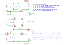
Attached is a LTSpice sim of a Monticelli output which i have used
for experimenting a few months ago.
In principle this works good, but you have to provide a current source input
to drive the circuit.
And the output transistors should be replaced by darlington transistors...
It is much simpler to increase the rails of the predriver by about 3 volt
and use a conventional EF...
Attachments
An alternative could be some variant of the 1976 class-AB bias loop technique of Han Huijsing and Frans Tol. Sense the currents through your output devices with small resistors, pass the resulting voltage through some non-linear circuit made with transistor arrays and use the result to control up or down the current through both output devices.
I meant something like this. No idea if you can get it stable, though.
Attachments
I dislike to waste power or headroom...
How often do you play to get *exactly* 49V peaks from a 50V supply?
I would think you probably play 5V to "60V" peaks from one day to another. So you usually have "unused headroom".
This is especially bad in linear class B because medium currents come from full voltage, thus "terrible" efficiency at anything less than full-power test tone (which is not pleasant music).
If it is a literally a matter of "wasted power", go class D.
In IC design with +-5 Volt rails every Volt is important.
But in Audio Amplifiesr with +-50 Volt supply rails, it is not worth
the trouble....
If you are concerned with power efficiency a Class-D Amp may be a better option.
How often do you play to get *exactly* 49V peaks from a 50V supply?...
Sure, it's a much smaller percent improvement on 50 V than 5 V.
And no doubt that class D is the way for major efficiency improvements.
But if I can find a small improvement then I will take it - if there's no downside.
That's the issue I want to explore.
Thanks for that.Attached is a LTSpice sim...
It is much simpler to increase the rails of the predriver by about 3 volt and use a conventional EF...
It is simple to increase the rails.
The seminal Bart Locanthi circuit used increased rails for the predriver and even added intermediate rails for the drivers.
But that does complicate the power supply a little, mainly the inconvenience of a custom multi-tapped transformer.
No one seems to bother with that any more.
The Monticelli OPS is conceptually more difficult but could lead to a fairly simple amplifier.
Best wishes
David
It is simple to increase the rails.
Ok. Don’t increase the rails.
Track them from the output.
If it is a literally a matter of "wasted power", go class D.
I've wondered about that; most amplifiers are used at low volumes most of the time, so quiescent current and rail voltage determine the dissipated power. How much DC current does a typical class-D amplifier draw at low volumes?
there are few ways to increase voltage supply for IPS part of amplifier,instead with additional transformer there could be used two capacitors and two 2W resistors... IPS doesn't need much current, and with increase of 10-15V per rail you can use all of output capabilities even if you have mosfet output. that might be a compromise you search. I might put a schematic of such amplifier, if you are interested in such solution.
Last edited:
It is not that hard to maximize energy efficiency: design the amplifier as voltage regulator with low intrinsic resistance and high amplification factor, borrow circuit ideas from industrial applications, use heavily doped devices at low bias current in push-pull configuration and voilà! The only thing that will suffer terribly is signal transfer...
How much DC current does a typical class-D amplifier draw at low volumes?
Comparatively orders with parasitic leak of MOSFET devices.
You might want to search patents, which can be tedious because the titles often use misdirection...Roy(al) Gosser but I can't think of other names just now.
I should have noted that I had done a bit of a patent search.
The authors may want to misdirect but the examiners do add references to prior art, so I was able to find later developments that were related to Monticelli.
That included Roy's work (Roy is his preference? No disrespect)
Some of these circuits rely on...
Yes, this was the sort of stuff I wondered if people had hints for.
Our DSL drivers...
I remembered you mentioned DSL drivers, how does the crest factor compare to music?
Best wishes
David
In the Monticelli circuit, the sum of the VBE... This is not different from the thermal stability issues you have in a conventional complementary emitter follower
Yes, that's pretty much as I see it too.
I don't know how exactly you would have to trim the quiescent current with two trimmable VBE-multipliers.
I expect the two Vbe-multipliers will be referenced/driven by a current source from rail to rail, so they track in unison.
Similar to your circuit in post #9.
Best wishes
David
Last edited:
Ok. Don’t increase the rails.
Track them from the output.
Hi Pavel
I think that some sort of variable rail is probably the ultimate solution.
Drive them from a class-D type switcher for efficiency and have the OPS always with low volts across the transistors to minimize power dissipation in the linear section.
Efficient and very low distortion.
I believe DIY member Harry Dymond did a paper on this, or similar.
Just a bit complicated at the moment
")
Maybe when I have time to study switchers/Class D in detail.
Best wishes
David
- Status
- This old topic is closed. If you want to reopen this topic, contact a moderator using the "Report Post" button.
- Home
- Amplifiers
- Solid State
- Monticelli or other Rail-to-Rail output?