Hi guys,
Have some problems with my NAD214. Some background: there was a speaker of 4 Ohms of DCres (although it states 8 Ohm on the speaker) connected to the NAD214 in BRIDGE MODE. Some distortion and one BAM sound. The speaker was disconnected fast.
Any more ideas guys? The main part is what can cause pin1 of TA7317P be at 0.7V and why POWER LED sometimes after a few minutes turns off at all (no RED or GREEN).
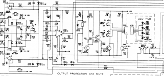
Please find the most important schematics part attached here.
Have some problems with my NAD214. Some background: there was a speaker of 4 Ohms of DCres (although it states 8 Ohm on the speaker) connected to the NAD214 in BRIDGE MODE. Some distortion and one BAM sound. The speaker was disconnected fast.
Now the NAD stays in PROTECTION mode, but the power LED sometimes changes between RED and GREEN when turning on/off the amplifier. After several minutes turns off at all (voltage across it drops). BRIDGE and SOFT CLIPPING LEDs works (but flashed at first).
Changed TA7317p protection IC (IC202). Tested and changed small capacitance bad CAPs around it.
The relay is new. All components contacts are resoldered. Switches and cables/joints too. Previously had the issue when cleaned a switch and sound came back.
Checked the resistors - values are good.
Even though the amp is in protection mode, it is working properly till the realay (checked with an oscilloscope and 1kHZ testing signal and the Idle Current is good for both channels).
What I found interesting that on the pin 1 of IC202 voltage is 0.7V, so MUTE is triggered. Changed diodes D212 and D211. Checked transistors on the power side of the amp. Nothing changed. Power supply voltages are good and noise-free (multimeter + scope).
No DC output on the pin2 and pin3 of IC202. Supply voltages good.
Any more ideas guys?
The main part is what can cause pin1 of TA7317P be at 0.7V and why POWER LED sometimes after a few minutes turns off at all (no RED or GREEN).Please find the most important schematics part attached here.
Attachments
there was a speaker of 4 Ohms...connected to the NAD214 in BRIDGE MODE. Some distortion and one BAM sound.
Have you checked out the output devices to make sure that one isn't shorted to ground and that the protection circuit isn't actually protecting?
Do you read any DC across your speaker output when you switch the amp on?
I had an Onkyo amp recently that would cycle in and out of protection and I could detect the DC briefly going above 1.5v before the protection IC operated. That one had shorted output transistors on one channel.
Try follow the voltages around - Do you get +52v at +VL (positive side of C331, Collector of Q339)? What voltage do you have at JP203/303 pin 6?
Are any of the fusible resistors toast? (LH AMP) R351, R353, R361, R359 / (RH AMP) R354, R352, R362, R360 / (Regulator) R203, R204, R205, R208.
Last edited:
*Check DC output on Pin2 and Pin3 of IC202 (those pins responsible for DC detection). No DC voltage (only few mVs, - detection range for IC ~1.1VDC).
*Checked channels with scope and sine signal at the input, both channels works properly (clear and undistorted sine wave comes until output relay) and the power transistors' Idle current stays around 22 mA (20 mA according to a service manual). So pre-amp and power-amp are working.
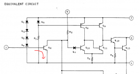
-> The only thing is 0.7V on pin 1 of IC202 where this pin is responsible for over-current protection. But where does this voltage or over-current come here if everything's OK.
*Checked channels with scope and sine signal at the input, both channels works properly (clear and undistorted sine wave comes until output relay) and the power transistors' Idle current stays around 22 mA (20 mA according to a service manual). So pre-amp and power-amp are working.
-> The only thing is 0.7V on pin 1 of IC202 where this pin is responsible for over-current protection. But where does this voltage or over-current come here if everything's OK.
But you can see if there's 0.7V on the pin1 the transistor inside drags pin8 to GND..
Changed C224, tested Q205,Q206,Q207 and Q208 transistors (OK). Nothing's helped. Now the POWER LED indicator doesn't work at all (expect mini flash of RED when turning the amp on).
Had the smoke between JP303 pin2 and pin3 (TH101 and VH-). Somehow they were shorted via a small burnt channel/solder. Fixed and nothing changed. Maybe a new IC202 is down again.
Write you soon IC202 voltages.
Attachments
So here are the voltages of IC202:
1. 0.73V
2. 0V
3. 0V
4. 0V
5. -0.73
6. 48.8V
7. 0V
8. 0.04V too litle?
9. 3.1V
UPDATE: Now no signal from pre-amp section. Idle current max of 12 (was 22 not changed by V-resistor). No POWER indicator color. Checked all supply voltages, all good.
1. 0.73V
2. 0V
3. 0V
4. 0V
5. -0.73
6. 48.8V
7. 0V
8. 0.04V too litle?
9. 3.1V
UPDATE: Now no signal from pre-amp section. Idle current max of 12 (was 22 not changed by V-resistor). No POWER indicator color. Checked all supply voltages, all good.
Last edited:
IC202 could be damaged - shorting pin 2 and 3 of J303 would have connected the +49v at pin 6 to -55v at the anode of D209 on the schematic. I'd check out these zeners (D208 and 209) as they were known to cause trouble on other models.
When IC Pin 1 is less than 0.7, the Pin 6 should go LOW and turn the relay on (Provides signal to Anode D210 via 2 thermal fuses). Have you checked this pathway yet - continuity check between IC202 Pin 6 to anode D210.
Check C226. The schematic has that one +ve lead to 0v - if you replaced it, check orientation. If you didn't replace it, test it out.
Print a copy of the schematic and highlight everything that was connected together by the short circuit that shouldn't have been and see if those components are good.
Check any burnt area for conductance of the pcb. Do power off continuity checks between traces that should be separate to make sure there aren't other shorts.
Unfortunately when something shorts out during fault finding, you have to start the testing process again and discard measurements and assumptions of 'good' components that you've already made - especially when the unit's behaviour changes as yours has.
Good luck!
IC202 could be damaged - shorting pin 2 and 3 of J303 would have connected the +49v at pin 6 to -55v at the anode of D209 on the schematic. I'd check out these zeners (D208 and 209) as they were known to cause trouble on other models.
When IC Pin 1 is less than 0.7, the Pin 6 should go LOW and turn the relay on (Provides signal to Anode D210 via 2 thermal fuses). Have you checked this pathway yet - continuity check between IC202 Pin 6 to anode D210.
Check C226. The schematic has that one +ve lead to 0v - if you replaced it, check orientation. If you didn't replace it, test it out.
Print a copy of the schematic and highlight everything that was connected together by the short circuit that shouldn't have been and see if those components are good.
Check any burnt area for conductance of the pcb. Do power off continuity checks between traces that should be separate to make sure there aren't other shorts.
Unfortunately when something shorts out during fault finding, you have to start the testing process again and discard measurements and assumptions of 'good' components that you've already made - especially when the unit's behaviour changes as yours has.
Good luck!
Thanks for ideas!
D208 and D209 is OK. Continuity from pin 6 of IC202 to D210 also.
What I found by measuring resistance, that there is some between TH101 pins and TH102 pins of JP203 and JP204 when JP303 and JP304 are disconnected... Cleaned between solder with a sharp tool and iso-propil alcohol. No more resistance (infinity). I suspect my soldering paste or its mix with old nad soldering flux - somehow it's conductive... Now I get my relay turning on and then fast turning off and then turning on steadily at constant rate (along with RED to GREEN to RED LED indicator).
Some news: when JP201 disconnected from JP301 - RED indicator and no relay clicking. When connected - magic described above starts. JP202 and JP302 connection doesn't matter. Some voltage (0.2V on pin2 of IC202 when relay clicking - will check with scope for impulse amplitude). Pin 1 of IC202 now -0.6V seems magically OK.
Sounds like there could be a short to GND that gets sent to earth when you connect the RCA.
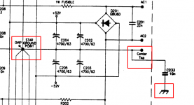
NADs are usually double insulated (no chassis ground) and they have 0V and transformer secondary centre tap connected to chassis via the C233.
I would check the condition of C233, see if there is any voltage between chassis and earth, check for connection between RCA input signal ground to chassis.
Does the amp work again if you connect the chassis ground screw terminal to earth with the RCA disconnected?
Sounds like there could be a short to GND that gets sent to earth when you connect the RCA.
NADs are usually double insulated (no chassis ground) and they have 0V and transformer secondary centre tap connected to chassis via the C233.
I would check the condition of C233, see if there is any voltage between chassis and earth, check for connection between RCA input signal ground to chassis.
Does the amp work again if you connect the chassis ground screw terminal to earth with the RCA disconnected?
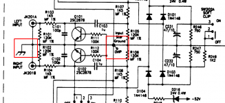
Checked C233, it's good, but I replaced to a new one just in case. I'm confused why this cap is used to isolate 0V from chassis when RCA 0V is connected to the chassis (see pictures attached)
When everyhting is connected 0V everywhere is short to chassis.Attachments
- Status
- This old topic is closed. If you want to reopen this topic, contact a moderator using the "Report Post" button.
- Home
- Amplifiers
- Solid State
- NAD 214 Protection