The saga of nutty amplifiers continues...
GainClones are good because they wrap a whole lot of circuitry into one tidy, easy to use package that has reasonable performance. Bridge amps are good because you can get twice the voltage swing and twice the slew rate than otherwise. Current dumping is good because you can easily use elephant-size output devices but without any concern about biasing, device matching, crossover distortion etc etc. Circlotrons are good because you can use two *identical* NPN or N-channel or tube devices, not an N-channel and an approximation of it in P-channel form. What's more, N-channels can be had in =seriously= big sizes and are cheaper than any wussy P-channel.
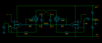
So then, what simply must be done is to roll all these ideas into one; the result being presented here. Actually I haven't built one yet because the idea only came to me in a flash this afternoon. The way it works may not be immediately obvious but I have had people way nore experienced than me look at it and it appears to be sound.
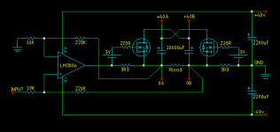
OK, I wont ramble on. The rails for the power opamps could be as much as +/- 40v because the opamps will not be drawing much current. The bulk of the load current is supplied from the two floating supplies. Their voltage should be at least as much as the opamp rails i.e 40v each at whatever current rating the load demands.
This amp should be able to drive almost any impedance load - Just keep on putting speakers in parallel. You need more output current? Just use bigger floating supplies and bigger mosfets. It's as simple as that! The sky is the limit. I'll try and post a SPICE cct in SIMetrix format soon. All comments welcome.
GainClones are good because they wrap a whole lot of circuitry into one tidy, easy to use package that has reasonable performance. Bridge amps are good because you can get twice the voltage swing and twice the slew rate than otherwise. Current dumping is good because you can easily use elephant-size output devices but without any concern about biasing, device matching, crossover distortion etc etc. Circlotrons are good because you can use two *identical* NPN or N-channel or tube devices, not an N-channel and an approximation of it in P-channel form. What's more, N-channels can be had in =seriously= big sizes and are cheaper than any wussy P-channel.
So then, what simply must be done is to roll all these ideas into one; the result being presented here. Actually I haven't built one yet because the idea only came to me in a flash this afternoon. The way it works may not be immediately obvious but I have had people way nore experienced than me look at it and it appears to be sound.
OK, I wont ramble on. The rails for the power opamps could be as much as +/- 40v because the opamps will not be drawing much current. The bulk of the load current is supplied from the two floating supplies. Their voltage should be at least as much as the opamp rails i.e 40v each at whatever current rating the load demands.
This amp should be able to drive almost any impedance load - Just keep on putting speakers in parallel. You need more output current? Just use bigger floating supplies and bigger mosfets. It's as simple as that! The sky is the limit. I'll try and post a SPICE cct in SIMetrix format soon. All comments welcome.
Attachments
Hi Graham
I think your circuit would work. But I assume that it would work better with BJT "afterburners" than using MOSFETs due to the lower opamp output-voltage needed to turn on the "afterburners".
Maybe differential feedback-takeoff would help as well, but I am not sure and have to think a little more on that one.
I would not call this one a current dumper. The original current dumping circuit uses frequency dependant parts to combine the two currents involved.
It resembles a principle called "Edwin amplifier" which was quite fashionable for DIY during the 70s because it didn't need any setting of bias-current and still achieve reasonable THD figures (though not high-end). I wonder why it isn't used more frequently nowadays because there are enough applications where its performance would suffice.
Regards
Charles
Hi Charles. Thanks for your observations. I'll see if I can find anything on this Edwin Amplifier. I use the term "current dumping" rather loosely, actually. 
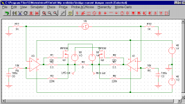
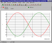
I ran a simulation with the opamps approximation LM3886's. The distortion comes out a little high but the waveform of the left side for example swings +23.012v and -22.968v. If I measured it differentially then it would probably be better because the RHS is a mirror image of the left of course. Output power was 132 watts on the imaginary workbench... It would go as high as 145 watts into 8 ohms just before clipping. The mosfets on the sim diagram are not really suitable, just what the demo SIMetrix simulator had.
I ran a simulation with the opamps approximation LM3886's. The distortion comes out a little high but the waveform of the left side for example swings +23.012v and -22.968v. If I measured it differentially then it would probably be better because the RHS is a mirror image of the left of course. Output power was 132 watts on the imaginary workbench... It would go as high as 145 watts into 8 ohms just before clipping. The mosfets on the sim diagram are not really suitable, just what the demo SIMetrix simulator had.
Attachments
Hi Graham
Below you see two basic variants of an Edwin output stage.
In the left variant the bias current is carried by the drivers and flowing through R1 and R2. This is a little like the circuit you want to use.
In the right version the bias current is flowing through the output stages and R3 and R4.
My guess is that the efficiency of the left variant is better at high levels than the right one. THD performance will most likely be better for the right one because the circuit properties change less when the circuit is going from A to B operation than for the left one.
I think there would be quite some possibilities for improvement with these circuits which went somehow forgotten lately.
Regards
Charles
Attachments
Hi Charles,
I think your right-hand circuit wouldn't really qualify for an EDWIN. The significance of the EDWIN, IIRC, was that the drivers would actully provide the output signal through the lowish R1, R2 until such time that the (sluggish) output devices were turned on. In the right-hand circuit, the drivers can't do that.
Jan Didden
Charles,
Yes, I see your point with the right-hand circuit on the easy bias. Actually, as you said earlier, the (huge) drawback of both circuits is the step in gain when the main outputs kick in. Feedback can only do so much to linearize the thing. But I am pretty sure the left is the EDWIN; I had just started audio DIY when it appeared, and I was mightily impressed that anyone could come up with such a clever scheme.
Jan Didden
Maybe the right-hand circuit might be improved by putting a series RC circuit across the diodes at the output, resembling a little closer the differential resistance of the diodes (O.K. they are current dependant but I guess you know what I mean) at higher frequencies. This might eventually lead to decreased crossover distortion.
Regards
Charles
Regards
Charles
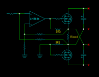
OK then. After posting this stuff last night I went to bed but forgot to take off my eXtreme Duty (tm) thinking cap. I kept on thinking for about an hour or so about if it was possible to make a version that only needs one power opamp and no phase splitter. First I thought about differential feedback from each side of the load with an additional opamp. Then this idea occurred to me. Drew it up today. Simulates OK. Just gotta find the time to make one.
One refinement in this version is the 3 volts bias battery on each gate lead. Assuming the gate threshold voltage is 4 volts, the voltage drop across the 3r3 resistors only has to now go as high as 1 volt before the mosfets start helping. I reckon a pair of those little CR2032 batteries like on computer motherboards would be ideal for this. The current drain on them is virtually zero. If logic level mosfets were used they would not be as necessary. Perhaps a single 1.35 volts mercury cell would be the way to go. I did read somewhere that these kind of mosfets have higher transconductance than normal ones so that would be good.
Another thing - if bipolar transistors were used instead of mosfets then it would be interesting to see what sort of HF performance they gave because there is quite a reasonable amount of reverse base drive available to speed up turnoff.
Attachments
Re: Mmmm..... symmetry....
Sorry if I am being stupid, but could you label the power connections on the right hand side of the latest two diagrams?
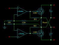
Circlotron said:Sometimes a circuit looks all that much clearer when it is drawn a different way. Redrew both single ended and bridge version today. Looks way nicer. I wonder though, whether green wires and aqua coloured fets will sound ok.")
Single ended.
Circlotron said:Bridge version.
Sorry if I am being stupid, but could you label the power connections on the right hand side of the latest two diagrams?
Circlotron said:Yep. Each of the electro's on the right is fed from a *floating* 40 volt DC supply. Polarity is as per the caps, of course. Again, must be floating.
You gunna be the first to try one out?
So you need two seperate power supplies, with non-connected grounds?
Its on my list of projects, after painting my sub. 145W sounds good.
You are right about it looking clearer redrawn.
Just a sidemark
I stumbled over the 1970 Elektor mag where they described the Edwin amp. According to this, the right schematic I posted does also qualify as Edwin amp. Graham's amp would also qualify as some sort of Edwin amp.
It is astonishing that, apart from the Quad current-dumping amp, not many attempts have been made to build class AB amps without need for bias-setting.
Regards
Charles
OPA541/9 opamp looks just fine to me.
I only mentioned the '530 mosfet because the simulator offered that one and there are way bigger ones available. I didn't choose it on purpose. Basically you could use as big a mosfet as you can find.
If you use a 4 ohm load at +/- 40v rails then the peak current will be 40/4 = 10 amps. The fet needs to have a minimum of 80v rating. Worst case for a reactive (i.e. real world) load is the current will be 90 degrees (usually) lagging, so at full blast the mosfet cops 10 amps at the output voltage zero crossing when it has 40 volts across it. 10x40 = 400 watts instantaneous (not continuous) dissipation when you are making 200 watts output power. Whatever the dissipation rating of the fet, provided it has enough voltage and current rating. it will be safe to supply 50% of this wattage rating as output watts into the ugliest load you can find.
I only mentioned the '530 mosfet because the simulator offered that one and there are way bigger ones available. I didn't choose it on purpose. Basically you could use as big a mosfet as you can find.
If you use a 4 ohm load at +/- 40v rails then the peak current will be 40/4 = 10 amps. The fet needs to have a minimum of 80v rating. Worst case for a reactive (i.e. real world) load is the current will be 90 degrees (usually) lagging, so at full blast the mosfet cops 10 amps at the output voltage zero crossing when it has 40 volts across it. 10x40 = 400 watts instantaneous (not continuous) dissipation
when you are making 200 watts output power. Whatever the dissipation rating of the fet, provided it has enough voltage and current rating. it will be safe to supply 50% of this wattage rating as output watts into the ugliest load you can find.Circlotron said:OPA541/9 opamp looks just fine to me.
I only mentioned the '530 mosfet because the simulator offered that one and there are way bigger ones available. I didn't choose it on purpose. Basically you could use as big a mosfet as you can find.
If you use a 4 ohm load at +/- 40v rails then the peak current will be 40/4 = 10 amps. The fet needs to have a minimum of 80v rating. Worst case for a reactive (i.e. real world) load is the current will be 90 degrees (usually) lagging, so at full blast the mosfet cops 10 amps at the output voltage zero crossing when it has 40 volts across it. 10x40 = 400 watts instantaneous (not continuous) dissipation
So, any N channel MOSFET rated at 80v, 10A and 400W, or better.
ok.This would require a serious power supply... 1kw per amp, or would it need more like 1kw per rail, per amp?
- Status
- This old topic is closed. If you want to reopen this topic, contact a moderator using the "Report Post" button.
- Home
- Amplifiers
- Solid State
- BridgeClone with current-dumping circlotron afterburner :-)