LM13700 provides a simple transconductance amplifier that can be used as the first stage in a three stage amplifier. However, LM13700 is rated at 0.5% distortion as its differential input is one of the simplest.
Are there other chips that provide a differential stage but use other more complex configurations? I am after something like the Complementary Feedback Pair or better.
Are there other chips that provide a differential stage but use other more complex configurations? I am after something like the Complementary Feedback Pair or better.
Are there other chips that provide a differential stage but use other more complex configurations?
You can try 5-th pin of AD844 or 8-th pin of LM318.
> LM13700 is rated at 0.5% distortion
At fairly high input and NO overall NFB.
See Fig 13 in the datasheet. 0.5% happens at 30mV input. At 5mV input it is 0.01%.
Given 30dB-40dB overall NFB the THD will be in the point-oh range.
Input stages nearly this simple are everywhere in audio. I believe Self (or Cordell?) consider alternate input topologies and find specific uses but no general "fancier is better" conclusion.
The drawbacks of LM13700 are low maximum voltage and NO way to control the input stage's Gm/Ie ratio. Bipolars have SO much gain that for most high-NFB audio amplifiers we want to reduce the Gm without reducing current (which would reduce slew rate).
The LM13700 is just a dozen 10-cent parts; you can as easily wire-up an appropriate input stage yourself.
SN74AHCU04. At a given signal voltage, it distorts somewhat less than an undegenerated bipolar differential pair, but more than a CFP with feedback resistors.
SN74AHCU04 as a cheap FET differential pair
In any case, why do you prefer an IC over a discrete input stage?
SN74AHCU04 as a cheap FET differential pair
In any case, why do you prefer an IC over a discrete input stage?
Last edited:
An IC is a neat way to bundle components together. Besides that, a well tried and tested chip is a design advantage for the inexperienced like me.In any case, why do you prefer an IC over a discrete input stage?
Another reason is the limited transistor selection range for high voltage small signal transistors. If I lower the voltages on the input stage I should have a far wider choice of transistors. The other reason is the unnecessary heat stress on the transistors themselves. My aim is to use droppers at the high (+/- 85V DC) supply rails to get +/-15V. I will use the usual wire-wound resistor, Zener diode, decoupling capacitor arrangement. This also should provide me with a virtual 0V rail that is completely isolated from the real 0V rail.
To get the signal to the high voltage VAS I plan to use a unity gain stage at the ground. As you can see, a chip is seems the best choice for the way I plan to organise my circuit. A discrete input stage would require: a) a stage to couple its output and a unity gain at the ground.
An IC is a neat way to bundle components together. Besides that, a well tried and tested chip is a design advantage for the inexperienced like me.
Fair enough, I can understand it so far.
Another reason is the limited transistor selection range for high voltage small signal transistors. If I lower the voltages on the input stage I should have a far wider choice of transistors. The other reason is the unnecessary heat stress on the transistors themselves. My aim is to use droppers at the high (+/- 85V DC) supply rails to get +/-15V. I will use the usual wire-wound resistor, Zener diode, decoupling capacitor arrangement. This also should provide me with a virtual 0V rail that is completely isolated from the real 0V rail.
Here I don't understand you anymore; transistors on ICs often have less voltage handling than discrete transistors, so what's the advantage of an IC?
To get the signal to the high voltage VAS I plan to use a unity gain stage at the ground. As you can see, a chip is seems the best choice for the way I plan to organise my circuit. A discrete input stage would require: a) a stage to couple its output and a unity gain at the ground.
I guess I'd need a schematic to understand what you mean here. Is your unity gain stage a voltage follower or a current follower (for example a common base stage)?
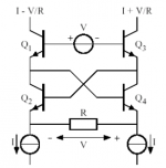
By the way, by adding a feedback resistor, a cross-quad made of four matched transistors can be changed into a voltage to current amplifier that's far more linear than an ordinary degenerated differential pair. You can find the matched transistors on transistor array ICs such as LM3046 or HFA3046. (I have never used an HFA3046 myself, but I could imagine it is more prone to oscillations than an LM3046 because of the high fT of the transistors on it.)
See the attachment, which comes from page 11 of https://ocw.tudelft.nl/wp-content/uploads/Translinear-circuits.pdf Apparently this circuit is known as Caprio's quad.
See the attachment, which comes from page 11 of https://ocw.tudelft.nl/wp-content/uploads/Translinear-circuits.pdf Apparently this circuit is known as Caprio's quad.
Attachments
There may be as modern version of NE540, and back in the 1970s there were professional amps that (tried) using op-amps as front-ends for power amps, but ICs have constraints thta do not work well in power amps. The most famous may have been the Crown DC300. The best of them was QSC's floating power supply.
1. They are limited to about 40 Volts rail to rail.
2. Monolithic chips make good (usually NPN) transistors only. Any PNP transistors have poor performance because they have to be made on the same N type substrate.
3. They are slow and have too much gain, making feedback stability almost impossible when you add the output stage.
A power amplifier has to be fast and high voltage, a place only a few chips designed for the task belong. The stuff you have to add to make a chip work in a power amp are more than making the whole thing from discrete transistors.
Indeed, it is a clever error-correcting scheme (a true one, unlike many well-known self proclaimed ones, if you see what I mean...), and a valuable one.By the way, by adding a feedback resistor, a cross-quad made of four matched transistors can be changed into a voltage to current amplifier that's far more linear than an ordinary degenerated differential pair. You can find the matched transistors on transistor array ICs such as LM3046 or HFA3046. (I have never used an HFA3046 myself, but I could imagine it is more prone to oscillations than an LM3046 because of the high fT of the transistors on it.)
See the attachment, which comes from page 11 of https://ocw.tudelft.nl/wp-content/uploads/Translinear-circuits.pdf Apparently this circuit is known as Caprio's quad.
It can be somewhat difficult to tame, because of the ~∞ transconductance and other unpleasant idiosyncrasies, but member Eva came up with a version that eases some of the issues:
♫♪ My little cheap Circlophone© ♫♪
I dubbed it the Evaquad, because she clearly was the originator of this version.
Unfortunately, Eva doesn't seem to be interested anymore in analog design, which is a shame given her talents, but that's her choice: she is now in love with class D topologies, but she might come back to her earlier loves (let's hope so)
A high frequency version of the CA3046 exists: the CA3127, and for truly masochistic people, Plessey also made an even faster version (beware: none are pin compatible with the 3046)
The circuit I am posting omits the voltage droppers that must be used to operate the LM13700 chip.
Please note I am not a qualified engineer. At the moment I am perplexed trying to make sense of what I am reading. Douglas Self mentions 'poles' and 'zeros' and bases most of his explanation on them. I consulted another book to understand what these are and it seems they are numerical constants in a quotient of two polynomials. Notwithstanding that polynomials are not the hardest thing in mathematics, I cannot imagine how to get the terms in the polynomial quotient formula for an actual amplifier. Mine only have one Miller Integrator with only one capacitor, so I must have only one 'pole', whatever that means.
To make it short, unless I learn how to create a plot of gain vs frequency and phase vs frequency for my amplifier, I will be only groping in the dark with an extremely slim probability of success. Needless to state, I do not only want an amplifier that supplies a sound signal to an output, but I want that signal to be clean and as distortionless as possible.
In a previous post I was asked why I want to avoid using input high voltage transistors. The reason is their high voltage counterparts are not so easy and common to find. I also think a low voltage input stage reduces unnecessary stress on the input. So, my options are two: a ready made chip or an input stage made of discrete low voltage transistors.
Attachments
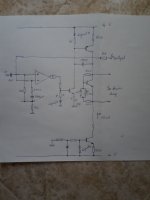
The circuit I am posting omits the voltage droppers that must be used to operate the LM13700 chip.
The circuit works just fine. With an ordinary op amp - doesnt need to be an OTA although one will work. Bulletproof op amps like the 5532 and LF 35x are often used because faults in the amp can apply high voltages which can destroy more delicate units. Whatever your poison, force the op amp’s output into class A over its operating range (usually only a small voltage swingJ to get maximum benefit of this arrangement.
For stability you do need to add lead compensation - a small cap either from the output of the amp or the output of the VAS to the summing node (- input). Usually only a few pF. It also helps to reduce the gain following the op amp somewhat. Local feedback to the emitter of lthe level shift transistor is usually the best way of accomplishing this. Approximate (or exact) pole zero analysis will tell you the stable range for C (and the resulting BW), but even by experiment isn’t that hard to optimize once you’ve done one or two.
...I am perplexed trying to make sense of .... 'poles' and 'zeros' .... I consulted another book ....numerical constants in a quotient of two polynomials. Notwithstanding that polynomials are not the hardest thing in mathematics, I cannot ....
The original chisel to organize these concepts is math heavy. We can skip that.
A pole is a bend, an up-bend, in the frequency response plot.
ALL amplifiers have one. This because no amplifier works to infinite frequency, and no amp has infinite gain. So a Simple Amplifier has a flat region, then a bend, then a falling region. The bend is the pole.
For completeness: we can also arrange reactances to have a falling response which levels-out. This is a zero.
In real life we need a dozen+ amplifier stages to get from microphone to loudspeaker. We cluster these in sub-units: preamp, line-amp, power-amp. While each sub-unity could be a cascade of simple stages with no overall NFB, NFB over multiple stages is such a powerful tool that we "always" have NFB over multiple stages.
Cascades of simple amplifiers will have multiple poles. Each pole contributes phase shift rising to 90 degrees when infinitely far from the pole.
A simple (and non-real) stage can only have 90 deg which even far-out is more negative than positive and thus stable.
Two simple stages will be two poles and at far-out will be 180 deg phase shift. We risk our negative feedback turning positive at some high frequency. Which will oscillate. In fact two ideal poles never reaches 180 deg, and the gain will be too far down to support oscillation. However the response may rise excessively at some point, which is excited, gives troubles. And all real amplifiers have "insignificant" poles at much higher frequencies (there is always the physical length around the loop) so 89deg + 89deg + 2deg makes 180 degrees and (if gain is sufficient) wants to sing.
Three stages with poles at the same frequency can oscillate with not much gain. 60 deg phase shift happens when gain is 1/3rd of max, so 3 stages and gain of 27 will sing--- the Phase Shift Oscillator.
A low-THD Hi-Fi power amp tends to four stages. The pole of the fat output devices tends to be low, and we usually have a Darlington or similar 2-stage affair here. We normally select the first 2 stages pretty-fast, then use "compensation" so that they act like a single-pole response, getting loop-gain down before the fat outputs add too much phase shift.
Oh, there are bass poles too. Not because of universal law (like no infinite frequency) but because Audio does not include DC, DC makes trouble, so we tend to block it. This is more a problem in tube amps where DC block between stages can be devilish. The usual modern (>1970) loudspeaker power amp has one bass pole inside the loop and that's no problem.
Raimondo Caprio is DiyAudio member. His crossquad circuit was published in 1973 : Precision differential voltage--current convertor - IET Journals & MagazineApparently this circuit is known as Caprio's quad.
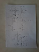
From this discussion and other threads, I am realising that using an IC or a low voltage input stage is going to increase circuit complexity without achieving nothing of value performancewise. Therefore, I am deciding to use a high voltage input stage as suggested several times. This means, I need to get hold of some high voltage input transistors. I also need high voltage transistors suitable to be used for a VAS using the same high voltage. The voltages of the supply are +/- 85 volts DC. So, I will need transistors that support 2 * 85V = 170V. I am aiming at 200 volts or more.
The input stage will be the usual current source (6mA as repeatedly suggested by Douglas Self), emitter degenerated differential pair, and the differential output will be taken from both tails of the differential pair. For the differential output I will use an emitter degenerated complementary pair with their bases connected at the differential outputs. I will also use diode biasing or if better, an amplified diode. The input must pass linearity tests using linear correlation mathematical techniques. I will make my test using DC voltages, and if possible, extrapolate for AC conditions.
My aim is to make sure I get an input that is extremely linear before moving to the next stage.
Congratulations, you have realized an important point about amplifiers. Every stage adds a pole to the feedback and makes it harder to stabilize the circuit, which means a more aggressive dominant pole, which means a low slew rate. ICs contain several stages and are usually compensated to be just stable with feedback around themselves without the addition of extra stages.
There are several high voltage signal transistors available but you may want to consider cascoding the diff-amp (pair) to reduce the voltage on them. The pole from a cascode stage is usually far above the diff-amp so it doesn't add a lot of phase delay.
However +/-85V means you are making a 900 Watt amplifier, so you will require about 18 power transistors per channel??? There is also the SOA effect at high voltage on power transistors, which cripples there current capability. A 20 Amp BJT transistor may suffer secondary breakdown at 2 Amps with VCE > 50 Volts. MOSFETs have better SOA, but most still have limitations. Class G and H amplifier were designed to deal with SOA problems, as well as better thermal efficiency. Remember that power transistor current is rarely in phase with the output voltage because loudspeakers are highly reactive (inductive or capacitive). This means that you may see the peak current and peak voltage on transistors at the same time, unlike when driving a resistor.
It is difficult to find a schematic on line that does not have something wrong with it. But this one has the input arrangement I had in mind.
http://circuitscheme.com/wp-content/uploads/2015/04/2000W-Power-Amplifier-Circuit-Diagram.jpg
But +/-85 Volts is a recipe for spectacular failures. I suggest you build a few smaller amps before you blow up a lot of expensive parts, like maybe +/-20V.
http://circuitscheme.com/wp-content/uploads/2015/04/2000W-Power-Amplifier-Circuit-Diagram.jpg
But +/-85 Volts is a recipe for spectacular failures. I suggest you build a few smaller amps before you blow up a lot of expensive parts, like maybe +/-20V.
Chips for differential stage
What about below chips?
SMD 5962-07222
SMD 5962-08218
SMD 5962-84185
it carries MICROCIRCUIT, LINEAR, WIDEBAND, DIFFERENTIAL OPERATIONAL AMPLIFIER, MONOLITHIC SILICON
Digital Fabric Printing, Digital Textile Printing - Rise Textile
What about below chips?
SMD 5962-07222
SMD 5962-08218
SMD 5962-84185
it carries MICROCIRCUIT, LINEAR, WIDEBAND, DIFFERENTIAL OPERATIONAL AMPLIFIER, MONOLITHIC SILICON
Digital Fabric Printing, Digital Textile Printing - Rise Textile
- Status
- This old topic is closed. If you want to reopen this topic, contact a moderator using the "Report Post" button.
- Home
- Amplifiers
- Solid State
- ICs that provide the first stage?