Excellent explanations ilimzn.
What is connection point of that double shield. A always do that, but cant tell which conection point is the best. So i tried to connect it on rxa gnd or on chasis...closest screw on chasis. Sig gnd is isolated with 10r with star gnd on pcb from there goes to power supply pcb gnd. From there also to chasis. How do you suggest at dual mono config. 1 transformer with 8 outputs. Transformer is isolated and it is connected to chasis. At high biased amps i get sometimes small buzz when i connect it to dac preamp that has breaker isolated gnd. If i use power cord without gnd. Buzz iz 0.
What is connection point of that double shield. A always do that, but cant tell which conection point is the best. So i tried to connect it on rxa gnd or on chasis...closest screw on chasis. Sig gnd is isolated with 10r with star gnd on pcb from there goes to power supply pcb gnd. From there also to chasis. How do you suggest at dual mono config. 1 transformer with 8 outputs. Transformer is isolated and it is connected to chasis. At high biased amps i get sometimes small buzz when i connect it to dac preamp that has breaker isolated gnd. If i use power cord without gnd. Buzz iz 0.
@ilimzn: if we ground the chassis at the rca's (the easiest might then be un-isolated rca), couldn't we then add another diode bridge in between the chassis and the 0v common point of the PS ? Then a breakdown from primary to secondary would have a more robust path to earth. Indeed, I wouldn't trust the low current section of an amp PCB to carry fault current.
Excellent explanations ilimzn.
What is connection point of that double shield. A always do that, but cant tell which conection point is the best. So i tried to connect it on rxa gnd or on chasis...closest screw on chasis. Sig gnd is isolated with 10r with star gnd on pcb from there goes to power supply pcb gnd. From there also to chasis. How do you suggest at dual mono config. 1 transformer with 8 outputs. Transformer is isolated and it is connected to chasis. At high biased amps i get sometimes small buzz when i connect it to dac preamp that has breaker isolated gnd. If i use power cord without gnd. Buzz iz 0.
Does the DAC/Pre hum if there is nothing connected to it's inputs?
Yes, also, i had usb connection, spdif or optical or no input connection. It is small but hearble buzz...not *classical* large loop buzz. Dac gnd that is screwed to chasiss is isolated with just one diode and 10R to IEC gnd. I think another diode will not bring improvement.
I always use all connection power cords to all components. Sometimes i must use GND not connected cable for DAC-preamp for totaly silent result. Power amps are always full grounded. If power amp has no rca connection it is also silent.
Thank you for your answer.
I always use all connection power cords to all components. Sometimes i must use GND not connected cable for DAC-preamp for totaly silent result. Power amps are always full grounded. If power amp has no rca connection it is also silent.
Thank you for your answer.
@ilimzn: if we ground the chassis at the rca's (the easiest might then be un-isolated rca), couldn't we then add another diode bridge in between the chassis and the 0v common point of the PS ? Then a breakdown from primary to secondary would have a more robust path to earth. Indeed, I wouldn't trust the low current section of an amp PCB to carry fault current.
It would be mandatory, but as i said, this is rarely the proper way to do it, only if there is no alternative.
In dual mono constructions, the input connector grounds are sometimes all connected together and the input connectors brought close to do this, in order to provide a common ground reference on the input connectors. Since this is the only common point, I have seen it also be connected to the chasis and the earth loop breaker. In this case, and especially if it's a multi-channel amp with a large transformer, it is almost mandatory for the transformer to have that shield/barrier between primary and secondary windings, this time in order to prevent capacitive coupling between primary and secondary.
There is a point of contention about where to connect the trafo shielding wire, to the common chasis point (where the earth loop breaker goes) or directly to earth.
It should be noted that ordinarily, in multiple channel situations where the channels are totally isolated (including PSU), one would probably do better having the grounds separate and connecting each to earth through it's own loop breaker. However, with multichannel installations, the amount of cabling can be a problem, also there might be multiple connections of the same source to multiple amps, implying non-trivial cable routing and possibly multiple outer loops through ground wiring in the interconnect cables. This may be the reason why the 'all input grounds connected' solution seems to appear often.
In the light of the above, I should mention that so far we have assumed the earth return is properly implemented in the installation, this is not always the case - even though the installation is done according to rules.
One typical problem are cable TV/CCTV/internet distributions in buildings. There are differences in how the rules are interpreted. In any case, the earth return is connected to the neutral wire, usually on the distribution board in each apartment or floor. The telecom cable will, however, be grounded only at one point. If it is on the bottom floor or cellar where it gets into the building, there will be little voltage difference between it's shield (ground) and earth on the first floor. But on the last floor, the voltage drop of all the loads in all the floors has added up in the neutral wire, and the earth is usually connected locally - now there could be a couple V or more difference. And if you connect this to, say, a TV and want to run audio through your system, first you get a huge loop throughout the whole building as the earth connects to the shield of the cable, and then this defines is the ground on the audio connectors on your TV, as they will normally all be connected to the internal TV metalwork (chasis) directly. And - it can get worse. The TV cable might be connected to earth in the local distribution point, which might not even be in the same building and can be hundreds or even thousands of meters away - with corresponding size of the earth loop, and all sorts of earth currents.
A lesser but still insidious problem are desktop PCs (and sometimes also laptops, plugged into mains power) and USB ports - the shield on the USB cable is directly tied to the chasis of the PC which is in turn as a rule directly tied to the earth return. So guess what happens when you plug this into your USB capable DAC - where the USB shield is almost as a rule connected to the RCA output ground.
These problems neatly multiply if you also use a coax digital cable from, say, a cable TV box to your DAC, in order to get digital sound from the TV or radio.
There are VERY few DACs that have an isolated USB port, and almost no cable boxes that have a transformer coupled digital output.
You are right ...another big problem is local loop. In our city, town if we have cable internet connection for example. So tv coaxial cable comes into apartment than is splitted with splitter to TV and router and radio, offten few meters apart. You have computer ...in my case RPI connected with lan cable to router and via usb to dac. As soon as i connect hdmi to tv i get huge loop buzz beacuse of internal apartment loop antenna. If i disconnect antenna from TV... silence. But because i dont need hdmi, which is disabled in settings because of better SQ, i don*t wory about that. Other must install antenna gnd braker for zero hum result.
@aparatusonitus : the rationale to sense the ground at the output connector of the pcb is coming from this page by Tomchr: LM3886 chip amp grounding.
On a properly laid out pcb, those two points should be close and linked by a low impedance track or a groundplane anyway.
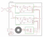
@ ilimzn : if I follow you correctly, that leaves us with the attached scheme which would be valid for most cases ? Or should I add a bridge from the RCA input gnd to chassis, so that everything has a low impedance path to earth in case of a major fault ?
On a properly laid out pcb, those two points should be close and linked by a low impedance track or a groundplane anyway.
@ ilimzn : if I follow you correctly, that leaves us with the attached scheme which would be valid for most cases ? Or should I add a bridge from the RCA input gnd to chassis, so that everything has a low impedance path to earth in case of a major fault ?
Attachments
@aparatusonitus : the rationale to sense the ground at the output connector of the pcb is coming from this page by Tomchr: LM3886 chip amp grounding.
On a properly laid out pcb, those two points should be close and linked by a low impedance track or a groundplane anyway.
?
It looks like chip amp layout and connection differs quite a bit from convectional discrete high power amplifiers! Normally we take the input ground at the quietest point possible, or in some cases directly to the main supplies. We return the speakers directly to the supply. We connect the zoble network (not in your diagram) away from the input ground, preferably on the opposite side the rail caps from the input supply and we take the feedback connection as close as possible to the output inductor.
I'm experimenting now with a complete dedicated power supply for the input section of each amp to see if this lowers distortion numbers farther. It noticeably improves stereo separation having separate supplies for each channel. I haven't taken proper measurements yet, that will wait until the chassis is ready. I'm not a believer in testing an amplifier sprawled out on a test bench. Quite often those numbers change dramatically when you put everything in a box and try to run it.
@ jwilhelm: actually, a chip amp is just a quite classical amp in a very compact package. So pretty much everything applying to chip amps applies to any amp.
Btw, the output zobel is on the pcb in my diagram, see Rz/Cz, returning directly to the bypass caps.
Yes I see the zobel now. As I said your measurements are completely different to what I've normally seen, so something must be different in your situation. I'm not the only one seeing improvement returning the speakers directly to the supply and keeping the input ground quiet.
Well, obviously, this must be done properly. The connection between the speaker return, the bypass caps and the power supply ground on the pcb must be low in impedance.
Still, Tomchr is hardly alone in promoting such scheme. All the Hypex amps have speaker return to the amp. See for example the NC400 suggested wiring.
Still, Tomchr is hardly alone in promoting such scheme. All the Hypex amps have speaker return to the amp. See for example the NC400 suggested wiring.
I'll do some more in depth measurements when I get a chassis ready. The amp I'm assembling now doesn't actually have any input wiring. The input connector is part on the input board and protrudes through the rear cover of the chassis so I can't experiment with coupling the input barrels. Measurements of output noise with shorted inputs also change with these wiring schemes and to me are equally important as distortion numbers (I hate hum!). I always take some time to try to get the lowest possible measurement there.
As a side note, I normally build 250W amps and if I recall correctly ( don't remember 10kHz figures exactly) produce lower distortion numbers that what you measured, possibly this is part of the difference? Comparing apples to oranges? Tomchr has produced some exceptional low distortion numbers with some of his layouts but they aren't in the same power range amplifier.
As a side note, I normally build 250W amps and if I recall correctly ( don't remember 10kHz figures exactly) produce lower distortion numbers that what you measured, possibly this is part of the difference? Comparing apples to oranges? Tomchr has produced some exceptional low distortion numbers with some of his layouts but they aren't in the same power range amplifier.
@aparatusonitus : the rationale to sense the ground at the output connector of the pcb is coming from this page by Tomchr: LM3886 chip amp grounding.
On a properly laid out pcb, those two points should be close and linked by a low impedance track or a groundplane anyway.
@ ilimzn : if I follow you correctly, that leaves us with the attached scheme which would be valid for most cases ? Or should I add a bridge from the RCA input gnd to chassis, so that everything has a low impedance path to earth in case of a major fault ?
I’m curious, is it better to isolate the PE from chassis with the GLB (as shown here) or connect PE directly to chassis and isolate chassis from amp and psu circuit by the GLB (as done in the generic Pass diy psu and first watt builds)? Does it even make any difference?
The safest way to build your amp is to bolt the PE to the chassis close to where it enters the chassis. This way you have complied with the most important class I safety requirements. Then connect the 0V/ground of the PSU/AMP to the chassis via a GLB.
This provides a current path to PE in the case of a transformer failure.
Any ground wires from the transformer shields should also be connected to the chassis. These wires should be kept short as they potentially could interfere with the inputs.
This provides a current path to PE in the case of a transformer failure.
Any ground wires from the transformer shields should also be connected to the chassis. These wires should be kept short as they potentially could interfere with the inputs.
Last edited:
This is what I’ve done in the amps I’ve built as well. The reason I ask is the diagrams in this post showing the GLB between PE and chassis. Though it is not clear to me that they are not essentially equivalent, assuming short wires everywhere, and the posts mentioned don’t really address the question.
Quite often those numbers change dramatically when you put everything in a box and try to run itIt looks like chip amp layout and connection differs quite a bit from convectional discrete high power amplifiers! Normally we take the input ground at the quietest point possible, or in some cases directly to the main supplies. We return the speakers directly to the supply. We connect the zoble network (not in your diagram) away from the input ground, preferably on the opposite side the rail caps from the input supply and we take the feedback connection as close as possible to the output inductor.
I'm experimenting now with a complete dedicated power supply for the input section of each amp to see if this lowers distortion numbers farther. It noticeably improves stereo separation having separate supplies for each channel. I haven't taken proper measurements yet, that will wait until the chassis is ready. I'm not a believer in testing an amplifier sprawled out on a test bench. Quite often those numbers change dramatically when you put everything in a box and try to run it.
Agree,but if you have good numbers when testing out of the box you will have to try some better solutions inside the box.
")
Last edited:
- Status
- This old topic is closed. If you want to reopen this topic, contact a moderator using the "Report Post" button.
- Home
- Amplifiers
- Solid State
- The dozens schemes to wire an amp...