Dead amp that I brought back to life with a few new transistors, and new output devices (originals were toast).
As usual, I pumped in a square wave to look for anything funny, and was greeted with pronounced ringing on both the positive and negative edge at only 1KHz and a fairly low amplitude (a few volts output). At 20KHz, the ringing doesn't even have a chance to settle down before the square wave switches polarity.
Was quite suprised to see this, and have never had to battle something like this before. I wish it was as simple as a failed component, but both channels exhibit identical behavior, so I think that is out.
Perhaps someone can enlighten me as to the mechanism behind a ringing square wave...and perhaps suggest a remedy? Is this design so inherently unstable that the replacement transistors are too fast? Or are the replacements too slow?
Attachments
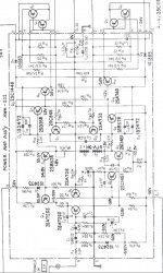
Maybe try some compensation from collector of Q5 to the base of Q2 and maybe half that amount from the output (before the output inductor) to base of Q2 while also removing the miller cap from Q5. The first cap may be 4.7-20pf while the 2nd may be 2.2-10pF, or so, in about a 2 to 1 proportion. 
EchoWars said:...I pumped in a square wave to look for anything funny, and was greeted with pronounced ringing on both the positive and negative edge at only 1KHz and a fairly low amplitude (a few volts output). At 20KHz, the ringing doesn't even have a chance to settle down before the square wave switches polarity.
Was quite suprised to see this, and have never had to battle something like this before. I wish it was as simple as a failed component, but both channels exhibit identical behavior, so I think that is out.
Perhaps someone can enlighten me as to the mechanism behind a ringing square wave...and perhaps suggest a remedy? Is this design so inherently unstable that the replacement transistors are too fast? Or are the replacements too slow?
My guess is the output transistors are faster, and are revealing mild instability that was masked before. If this is not an audible problem, don't worry about it. If you feel you must quell it, there are so many possible sources.
Here are some ideas. First I would try to figure out which stage is causing it, by looking down the chain from output to input until the ringing disappears. It is likely the previously inspected stage is the source and you can focus there.
My gut feel is that it originates in the output EF triple. I don't see any base stopper resistors between the predrivers and drivers, sometimes that can lead to mild instability. Sometimes just a 10 ohm resistor to the base will shut that down. Alternatively, you can try slowing down the drivers (Q9, Q10) with say 100 pF caps between base and collector, although that might just mask the problem you have revealed. You might consider those options.
If it seems the problem is elsewhere, there are a few other areas that seem a little out of control. The VAS seems undercompensated, that 10 pf (C7) on Q5 looks like eyewash to me (I would expect 100 pF, and it's pair mate has 47 pF). Sub in 100 pF as an experiment.
Some other random thoughts:
It could be the output inductor is underdamped, try a 1 ohm 5 watt there instead of 10 ohm (R41).
Is R42 open, from previous oscillations? If the amp was oscillating before, this could cook, effectively removing the cap and that cap may be needed for stability.
The input filter has only a 47pf cap, that does not do much to limit high frequencies coming in. Consider a 390 or 470 pF low pass input cap (C3).
Those are some thoughts. Good luck!
The original output transistors are 2SC1116A (10MHz) and 2SA747A (15MHz). The replacements are 2SD424 (5MHz) and 2SB554 (6MHz).
However, the replacements for the original 2SB528 (70MHz) and 2SD358 (ft unknown, probably around 70MHz) were replaced with 2SA794A (120MHz) and 2SC1567A (120MHz). Would that be enough to do it?
I dug around, and I have a couple of old driver boards with good 2SB528's and 2SD358's, which I'm gonna pull out and put in this amp. But before that, I'm going to check R42, and maybe even replace C11 with a .1µf cap. Couldn't hurt....
Re: Ringing
Forgot to reply...the ringing is there with either no load, or with an 8-ohm dummy load. There should be no oddball capacitances with enough magnitude to account for the ringing.johnnyx said:Could it be the output inductor ringing with soe load capacitance? If the frequency of the ringing is fairly low then this is probably it. Instability from the change of components would ring at a few megahertz.
EchoWars said:
I'll see if I can follow the signal from input to output and determine where the ringing starts.
Unless I'm mistaken, you'll see ringing all along the signal path unless you lift the feedback. And if you lift the feedback, the input signal should be considerably reduced.
And that's pretty much what I see...about the only place I don't see ringing is on the base of the input.Bill Fitzpatrick said:
Unless I'm mistaken, you'll see ringing all along the signal path unless you lift the feedback. And if you lift the feedback, the input signal should be considerably reduced.
I did calculate the frequency of the ringing...it's about 290KHz...
...looks like the designer tried to design a fast amp.
...fast transistors, small compensation caps.... compensation of
VAS reduced above 2.8Mhz, which might correspond to another
pole of the following current gain stage....
... combination of low compensation and relatively strong feedback...
All in all:
- difficult to calm down.
- already critical alignement mixed up by changing several
transistors.
I do not agree 100% that "let it ring except you can hear it", would be good. Is the ringing frequency very high? If yes, then this ringing
may also cause heat in the output stage as the power transistors
need some more microseconds for current decrease than for
increase...
For the first approach my proposals would be:
- increase the 10pf (C7 ?) in the VAS in small steps and
at the same time decrease R18 (keep C7 x R18 unchanged).
- if you reach C7=47pF and R18= 1.2kOhms without major improvement then check what happens if you keep 47 pf and go on reducing R18.
Good Luck
Markus
...there it is... 290kHz....
At this frequency the ringing may already cause some undesirable
heat, especially if you operate at higher levels.
So just be carefully.
How did you toast the old transistors?
Did you overload, short circuit, or somehow else stress the amp?
If it simply burned just during normal operation, without obvious reason, then I suspect that already the original design had ringing
issues.
15 years back when several fast amps entered the market and were
promoted to be the perfect solution, I saw an ultra fast high end amp cooking itself into death by high frequency oscilation, just because the wrong speaker wires were used. The capacitance of the cable caused additional pole and the compensation went unstable.....
Well, in fact I am quite conservative in this. I prefer non critical
compensation with an phase margin of 90° or more, even if I have
to work with less feedback for this....
Bye
Markus
or simply reduce feedback
another approach might be to decrease the feedback,
simply by increasing the closed loop gain.
I.e. change the feedback resistor (R23? cant read it).
Giving a big step here from 33k to 68k should also result in
less ringing......
OK, now we have flooded you with tons of proposals which might
turn out to be all rubbish.... hopefully not, but you never know until
real life examination is done.
No problem guys...
ChocoHolic..
I bought the amp dead. Was in beautiful condition, but one channel fried. I found shorted transistors in the dead channel, and leaky E-C junctions in the other. The drivers were also damaged, but I had originals of the same type to replace them with. Also a couple of pre-drivers were shorted. At this point, all transistors are original except the input pairs, and the final output devices.
I changed the Zobel cap to .1µf, and it made a small improvement. Not near enough to call it fixed, or even close. Going to leave it in anyway.
However, adding a 100pf cap from the base of Q5 to the collector makes a real improvement, and adding a 12pf cap across the feedback resistor almost eliminates the problem completely. With both caps in place, there is only a small amount of overshoot with a 10KHz square wave, and it settles down very quickly, about 1 cycle.
Does this fix make sense? Tempted to say 'well, if it works, it works', but is there another way I should approach this?
How about taking that 5.6K completely out and replacing with a 0-ohm jumper, and putting in a 100pf cap in place of the original 10pf C7?
... yes I think, your observations make sense.
Increasing the cap at Q5 defines the dominant pole in the bode plot.
But unfortunately the drawback of this are:
- higher TIM distorsions (input stage has to deliver more and signal in order to drive the slow follwing stages at high frequencies....)
- feedback at high frequencies is getting poor
This is the reason why this way of compensation has its limitations.
I would expect that the time constant of the 5k6 and the 10pf
are related to some other pole of the amp. So I would try to keep
the time constant of these two components constant. But probably
the difference will be very small and using a jumper instead of 5k6
could work as well.
12pf across the feedback is also fine, as it helps to bring the
phase of the feedback signal towards "earlier" (simply said...).
I think it would be OK to experiment with values up to
47pF here.
Looks like you may find a good combination of the compensation
across Q5 and the feedback.
Cheers Markus
....is there a reason why you don't want to set the 5k6 down to
560 ohms in combination with 100pF....?
Why would you prefer a jumper and 100pF?
For my taste the 100pF at this stage is already quite
high. The pole frequency will be given approx.
by R9 and C7 DIVIDED through the gain of the VAS!
R9 defines the driving resistance (if we neglect the output impedance of Q2). The gain of the VAS influences the resulting pole because
C7 has to be charged not only with the small amplitude of the
input voltage of the VAS input... No, it is seeing the full voltage
swing of the VAS output. More precisely the factor would be the gain+1, as the input moves to the other direction than the output...
....the same behaviour like a linear miller capacity.....
If we now caculate 100pF and 5k6 make 100kHz, dived by the gain of the VAS about 100 (?? no detailed idea just a number).
Tehn this means already above 1kHz the compensated gain of the VAS may decrease..... At 20kHz the voltage gain of the compensated VAS may be down to about 5..10 (again just a number)!
You can try to measure the signal at the input of the VAS and the
output of the VAS at 20kHz.
You will see at high frequencies the differential stage will have to deliver quite high levels. So a short fast signal at the input of the amp can drive the INPUT stage to clipping. TIM distorsion means transient intermodulation distorsion...... Even without hard clipping of the differential the distorsion of the input stage will increase with
the required signal level....
You see in frequency compensation, you cannot win.
You will always loose in one or the other way....

Don´t worry, these poor looking values are not a special
drawback of your amp. They are normal in most amps.
Many OP amps have the dominant pole even much lower than
1kHz.....
Bye Markus
560 ohms in combination with 100pF....?
Why would you prefer a jumper and 100pF?
For my taste the 100pF at this stage is already quite
high. The pole frequency will be given approx.
by R9 and C7 DIVIDED through the gain of the VAS!
R9 defines the driving resistance (if we neglect the output impedance of Q2). The gain of the VAS influences the resulting pole because
C7 has to be charged not only with the small amplitude of the
input voltage of the VAS input... No, it is seeing the full voltage
swing of the VAS output. More precisely the factor would be the gain+1, as the input moves to the other direction than the output...
....the same behaviour like a linear miller capacity.....
If we now caculate 100pF and 5k6 make 100kHz, dived by the gain of the VAS about 100 (?? no detailed idea just a number).
Tehn this means already above 1kHz the compensated gain of the VAS may decrease..... At 20kHz the voltage gain of the compensated VAS may be down to about 5..10 (again just a number)!
You can try to measure the signal at the input of the VAS and the
output of the VAS at 20kHz.
You will see at high frequencies the differential stage will have to deliver quite high levels. So a short fast signal at the input of the amp can drive the INPUT stage to clipping. TIM distorsion means transient intermodulation distorsion...... Even without hard clipping of the differential the distorsion of the input stage will increase with
the required signal level....
You see in frequency compensation, you cannot win.
You will always loose in one or the other way....
Don´t worry, these poor looking values are not a special
drawback of your amp. They are normal in most amps.
Many OP amps have the dominant pole even much lower than
1kHz.....
Bye Markus
I'm just going by what has made an impriovement in my bench experiments.....is there a reason why you don't want to set the 5k6 down to 560 ohms in combination with 100pF....?
Why would you prefer a jumper and 100pF?
Seems that if I use 100pf and 560 ohms...providing the same pole frequency...that I haven't gained anything. I also agree that a 100pf cap is a little large. The alternative would seem to be a compromise...perhaps a 47pf cap instead. Adjusting the resistor value would mean putting in a 1.2K resistor instead of the 5.6K, but I do not have the caps here to attempt this.
I'll order several different sized caps and see what they do.
EchoWars said:No problem guys...
... At this point, all transistors are original except the input pairs, and the final output devices.
Just a thought:
I see that you have done a lot of trials w/o getting the performance of the working channel but have you looked at the input pairs transistors... This is not neglectable. I noticed that the scjematics includes a compensation cap at Q1. This cap value may not be appropriate for the new transistor?
The Zetex transistors I used as replacements are rated at 100MHz ft just like the original 2SA726 ones. I have also added another compensation cap to Q1, and it changed nothing. The key here seems to be compensation on Q5 and/or a compensation cap across the feedback resistor.
Hi Echo!
100pF and 560 Ohms or 10pF and 5k6 is not setting the pole.
This time constant is setting the frequency above whitch the compensation network will stop it's influence (about 2.8MHz).
The pole is given by the driving resistance (mainly R9) and C7 and the
low frequency gain of the VAS (resulting in some single kHz).
But in fact, I would expect that you do not observe a major influence
if you use 560 Ohms or a jumper....
- Status
- This old topic is closed. If you want to reopen this topic, contact a moderator using the "Report Post" button.
- Home
- Amplifiers
- Solid State
- Taming Ringing...Square-Wave Response