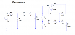
I've found versions of the attached input network in several amplifiers I've surveyed. It creates a low frequency rolloff at about 2Hz and high frequency rolloff at about 1.4MHz.
The combination of C3 and R5 creates a zero at about 2Hz and a pole at about 20Hz, which results in an increase in gain of about 1dB between those two frequencies.
What is the purpose of the C3-R5 combination?
The combination of C3 and R5 creates a zero at about 2Hz and a pole at about 20Hz, which results in an increase in gain of about 1dB between those two frequencies.
What is the purpose of the C3-R5 combination?
Attachments
What is the purpose of the C3-R5 combination?
Bootstrap the input impedance?
This is briefly touched upon in the 6th edition of Douglas Self's book Audio Amplifier Power Design, in the full schematic of the Trimodal Amplifier Figure 17.19 (p.442). I think it's a shame that he actually deleted his detailed explanation of the circuit, which appeared in the previous (5th) edition on pp.104-105 and especially Figure 4.24. Maybe between the 5th and 6th edition, D.S. changed his mind about the benefits/risks of the circuit (??) but, since he's still selling PCBs of the Trimodal Amplifier, felt that since it's still on the board it must be shown in the schematic too (??)
If it's mentioned in Bob Cordell's power amp book, I can't find it.
Nelson Pass used the circuit in the Threshold S300 power amp, and in the Threshold CAS-1 power amp, both of whose schematics are online and findable with Google.
If it's mentioned in Bob Cordell's power amp book, I can't find it.
Nelson Pass used the circuit in the Threshold S300 power amp, and in the Threshold CAS-1 power amp, both of whose schematics are online and findable with Google.
Bootstrapping, like jony wrote.
R3 + R4 = R6, so base currents give no DC offset as long as they match. As R3 + R4 and R6 are relatively low, you don't get much offset even when they don't match.
Thanks to the bootstrapping, there is not much AC voltage across R3, so the AC input impedance is reasonably high despite of the low R3 + R4.
When designed incorrectly (large input AC coupling cap and small bootstrap capacitor), the circuit may have an impedance dip down to about R3 + R4 at some subsonic frequency. Looking at the values in the schematic, I expect the circuit to have such a dip.
When designed well, you can get rid of the dip and make the response of the whole amp close to second-order Butterworth high-pass.
Last edited:
If my calculations are correct, using C3 = 470 uF, C1 = 2.2 uF and C4 = 2777 uF (practically 2200 uF + 470 uF) should get the response close to second order Butterworth, 3.8 Hz, with no deep input impedance minimum. I neglected some things, so you may still need some finetuning. You can scale the cut-off frequency by scaling all of C1, C3 and C4 by the same factor.
Last edited:
The bootstrapped input circuit in post #1 gives a high input impedance, while using low valued, matched resistors for low noise and low (delta_Ibase x Rinput) offset voltage.
A second way to achieve high input input impedance, low noise, and low offset voltage, is to use a JFET input stage and either an offset trimmer or a DC servo. This is the approach that Bob Cordell uses again and again in his book, which may be one reason why he doesn't discuss bootstrapped BJT input stages at all. This second way is also the approach Nelson Pass uses in his First Watt and Pass Labs amplifiers. He has ceased using the bootstrapped BJT input stages from his youth, waaaay back the Threshold days (1970s).
A second way to achieve high input input impedance, low noise, and low offset voltage, is to use a JFET input stage and either an offset trimmer or a DC servo. This is the approach that Bob Cordell uses again and again in his book, which may be one reason why he doesn't discuss bootstrapped BJT input stages at all. This second way is also the approach Nelson Pass uses in his First Watt and Pass Labs amplifiers. He has ceased using the bootstrapped BJT input stages from his youth, waaaay back the Threshold days (1970s).
This is briefly touched upon in the 6th edition of Douglas Self's book Audio Amplifier Power Design, in the full schematic of the Trimodal Amplifier Figure 17.19 (p.442). I think it's a shame that he actually deleted his detailed explanation of the circuit, which appeared in the previous (5th) edition on pp.104-105 and especially Figure 4.24. Maybe between the 5th and 6th edition, D.S. changed his mind about the benefits/risks of the circuit (??) but, since he's still selling PCBs of the Trimodal Amplifier, felt that since it's still on the board it must be shown in the schematic too (??)
Thanks for the references; I learned some useful stuff. Self explains that the bootstrapping raises the input impedance from 2.2K to about 13K, and mentions that most audio sources find 2.2K way too low. An alternative to bootstrapping is to use an input buffer that can drive 2.2K, but that has drawbacks. Comments?
I found a ratty copy of the S300 but nothing for the CAS-1.If it's mentioned in Bob Cordell's power amp book, I can't find it.
Nelson Pass used the circuit in the Threshold S300 power amp, and in the Threshold CAS-1 power amp, both of whose schematics are online and findable with Google.
I wonder who came up with this particular bootstrapping network back in the mists of time. It's pretty clever, and quite unintuitive to me.
Bootstrapping, like jony wrote.
R3 + R4 = R6, so base currents give no DC offset as long as they match. As R3 + R4 and R6 are relatively low, you don't get much offset even when they don't match.
Thanks to the bootstrapping, there is not much AC voltage across R3, so the AC input impedance is reasonably high despite of the low R3 + R4.
Ah, that's the key to intuitive understanding: not much AC voltage across R3 means that it looks more like a current source. This reminds me of a circuit designed by a guru who is long since retired. He used active circuitry to bootstrap some load resistors on a sort of diff amp, which made them look like current sources.
It does indeed. Is that a problem? The dip is about 3dB down at 20Hz.When designed incorrectly (large input AC coupling cap and small bootstrap capacitor), the circuit may have an impedance dip down to about R3 + R4 at some subsonic frequency. Looking at the values in the schematic, I expect the circuit to have such a dip.
Yes, I used your idea below and then modified it a bit. See my response below.When designed well, you can get rid of the dip and make the response of the whole amp close to second-order Butterworth high-pass.
If my calculations are correct, using C3 = 470 uF, C1 = 2.2 uF and C4 = 2777 uF (practically 2200 uF + 470 uF) should get the response close to second order Butterworth, 3.8 Hz, with no deep input impedance minimum. I neglected some things, so you may still need some finetuning. You can scale the cut-off frequency by scaling all of C1, C3 and C4 by the same factor.
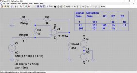
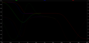
After fooling with simulation for awhile, I got the results below. Solid green is for the original values, solid red is yours, solid blue is after a bit of fiddling (C3=1000uF, C1=4.7uF, C4=1000uF).
Again the question is: is this bootstrapping really worthwhile?
Attachments
The bootstrapped input circuit in post #1 gives a high input impedance, while using low valued, matched resistors for low noise and low (delta_Ibase x Rinput) offset voltage.
A second way to achieve high input input impedance, low noise, and low offset voltage, is to use a JFET input stage and either an offset trimmer or a DC servo. This is the approach that Bob Cordell uses again and again in his book, which may be one reason why he doesn't discuss bootstrapped BJT input stages at all. This second way is also the approach Nelson Pass uses in his First Watt and Pass Labs amplifiers. He has ceased using the bootstrapped BJT input stages from his youth, waaaay back the Threshold days (1970s).
From what I've read, there's been much discussion, sometimes heated, about the relative merits of BJT versus JFET input stages. I have no experience with them as of now, aside from simulation in LTspice, but I spent the first half of my career at Tektronix designing exclusively with BJTs, so I have some prejudices.
")
It does indeed. Is that a problem? The dip is about 3dB down at 20Hz.
That depends on the circuit that drives the input and on whether there is much subsonic content in the signal. I would prefer not to have such a dip when it's easy to avoid it, but maybe that's perfectionism.
This is the circuit I use. It has approximately a second-order Butterworth response with 1 Hz cut-off frequency without any capacitors greater than 2.2 uF. The upper op-amp symbol is actually an almost discrete audio power amplifier. Mind you, R2 and the supply voltages of the TL071 limit how much main amplifier bias current the circuit can correct for. If needed, you can scale down R2, scale up R5 by the same factor and modify R1 such that R1 // R2 remains constant.
Attachments
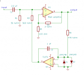
One thing I forgot to mention: for frequencies around 1 Hz there is gain from the input to the output of the TL071, so if you want the amplifier to be able to handle a full-scale sine wave at any frequency, you need to keep enough headroom to deal with that. Again, if needed scale R2, R5 and R1.
- Status
- This old topic is closed. If you want to reopen this topic, contact a moderator using the "Report Post" button.
- Home
- Amplifiers
- Solid State
- Input Network Question