good afternoon,
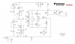
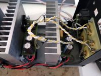
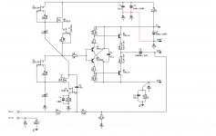
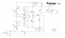
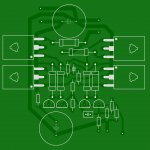
introduce my amplifier see attachment
Uin max RMS 2.8V
Pmax 70W (4R)
Ku 15dB
K (TND) 0.01%
circuitry in the form of vintage, sounding very good, who are interested in asking questions, who sees errors in topology - write ...
On the forum I happen rarely, I apologize in advance for the slow answers.
with respect
HenK
Attachments
Last edited:
Thanks for posting your work. A fresh and different design. Congratulations!
regards
Prasi
Ha Prasi ...new troubles on the road!
 , want to build this one as well
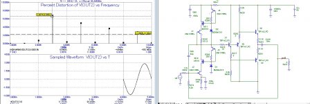
Hello Hennady,
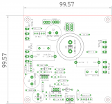
Could you kindly take a look at my drawing of your schematic and advise about
1. Grounding scheme
2. Resistor wattages of R9/R11. Except specifically mentioned wattages, I have used 0.5W package for resistors (10mm pitch).
regards
Prasi
Could you kindly take a look at my drawing of your schematic and advise about
1. Grounding scheme
2. Resistor wattages of R9/R11. Except specifically mentioned wattages, I have used 0.5W package for resistors (10mm pitch).
regards
Prasi
Attachments
Hello Prasi.Hello Hennady,
Could you kindly take a look at my drawing of your schematic and advise about
Wow, good work. I have some tips:
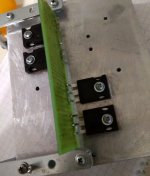
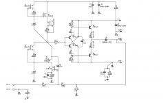
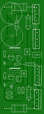
1) the arrangement of the elements D2,R5,J4,Q6,J1 end D1,R4,J2,Q5,J3,R16 according must be the same on the Plate
2) Cap C1,C2 should be near
3) with the help of R5 half of the power is adjusted, it can be either a resistance of 91Ω or 110Ω ohms so it is desirable to make it out of two for example 75Ω and 25Ω ohms, for tuning or 75ohm constant and 50 ohm treemer.
See attachment, I corrected.1. Grounding scheme
ok, 0.5W normaly.2. Resistor wattages of R9/R11. Except specifically mentioned wattages, I have used 0.5W package for resistors (10mm pitch).
regards
Prasi
these resistors determine the initial current of the output transistors, the higher they are the higher the current the higher.
see attachment:
Attachments
- Status
- This old topic is closed. If you want to reopen this topic, contact a moderator using the "Report Post" button.
- Home
- Amplifiers
- Solid State
- Amp Furious VaBAnk 70W