
I finally found some time to do this. Here are the results. Seems the K135's are ok, right?
Attachments
Its exactly the same method except this time you reverse all the supplies (which you can't do with your 6 volt output... see below).
If you look at post #88 last image you will see how it works. Just connect the FET test circuit to the power supply but with opposite polarity. Your meter + lead now goes to the plus terminal of the power supply, and all voltages you measure will be minus with respect that point. So far so good.
Your gate voltage will have to come from a preset that you place across the now -9 volt rail. Adjusting the preset would give a 0 to minus 9 variable gate voltage. You still retain the 1 meg from preset wiper to gate.
Ok, I have a few questions:
1. Am I connecting my meter negative lead to the +18 power supply teminal?
2. And am I using my meter positive lead to measure the bias and drain voltage, which will show negative voltage readings?
3. The COM terminal on the power supply still goes to the Source?
4. Where am I connecting the Drain to? Still the -18V terminal?
Last edited:
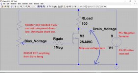
Like this. The only thing that has changed is the polarity of the supply. The preset gives you a variable gate voltage. We can't use the +6 terminal as before because that is now of the wrong polarity relative to what we want.
I don't need the 100K resistor and preset pot if I just raise the negative bias voltage from zero to -1V directly at the power supply, right?
So right now I have the following connections:
-18V to 1 meg to Gate. Starting at 0V.
+18V to 100 ohm resistor to Drain.
COM to Source and meter negative.
Not exactly ")
The Source has to go to the PSU positive terminal.
The Drain and its 100 ohm go the negative terminal. You also now measure ALL voltages from the positive terminal which becomes our reference point. That means you will see a variable negative voltage on the Drain as you alter your supply. So as before, we set it to around 9 volts.
The gate voltage has to be variable with respect to that positive terminal.
Another way to do it would be to use a fixed 9 volt battery for the main power supply. Battery plus to Source, battery negative to drain.
You could now connect the plus output of the power supply to the battery plus and the negative of the power supply via the 1meg to the gate. That should give you a variable gate voltage. Again all voltages are measured from the battery plus terminal.
If you do that then only connect the battery once the gate has been wired up. Leaving the gate floating (on a good fet) will almsot certainly turn the fet on and with a tiny 9 volt battery and 100 ohm load it will soon pull the voltage down.
If we are down to replacing FET's then I would definitely begin by removing all four from the channel being worked on and then begin replacement with a single pair only and make sure that works as expected and that it biases up correctly. When that is proved good, fit the second pair.
Also before fitting the replacements, be sure to set the bias voltage (voltage across the 150 ohm) to minimum.
This also seems a good time to get rid of those sockets and mount the FET's conventionally.
The originals are obsolete these days but alternatives exist. These are listed as replacements for the old 2SK/2SJ devices.
ECF10N20 - Metal Lateral MOSFET
ECF10P20 - Metal Lateral MOSFET
Of course, I rediscovered this recommendation to only replace one pair of FET's at a time after I had already replaced both pairs.
For presetting the bias voltage to minimum, I have P2 (a Bourns 3352) set to its max of 1k ohm, as measured between the wiper and leg 3. What voltage should I be aiming for across the 0.22 ohm resistors after power up? 22mV?
Speaking of which, my thought is to do the initial power on with my DBT and a 100 watt bulb.
Anything else I can/should do to safely test the new FET's?
For presetting the bias voltage to minimum, I have P2 (a Bourns 3352) set to its max of 1k ohm, as measured between the wiper and leg 3. What voltage should I be aiming for across the 0.22 ohm resistors after power up? 22mV?
I can barely read the schematic, you want the bias pot at zero resistance (shorted) this will saturate the bias transistor, you want minimum voltage across the gates to start. 22mv would be correct.
Speaking of which, my thought is to do the initial power on with my DBT and a 100 watt bulb.
The bulb is the way to go.
Mad
PS Double/triple check your work...
Ok, glad I asked about the bias pot. So adjust it to zero ohm initially.
Taking a step back for a moment, the TO-3 sockets I used here have integral metal threads for the mounting screws, unlike the phenolic type that had been in there. It doesn't seem like an additional washer and nut is necessary with this design, correct?
Taking a step back for a moment, the TO-3 sockets I used here have integral metal threads for the mounting screws, unlike the phenolic type that had been in there. It doesn't seem like an additional washer and nut is necessary with this design, correct?
A DBT is a very good idea. You may need to reduce the bias on the good channel though to minimise mains current draw.
Preset as minimum as mentioned above. Doing that places the fixed resistor (R36) between C and B turning the transistor on.
The sockets I'm afraid I can't advise on as they are something I would have to see first hand. However they work, make sure the basics are correct and that the transistor is electrically isolated correctly, that it is in good thermal contact with the heatsink and that the gate and drain wiring is the correct way around.
22mv across each 0.22 ohm gives 100ma per FET pair. If all seems OK then turn the bias back down to zero and readjust again correctly when on full mains voltage (no bulb).
Attachments

Thanks Mad and Mooly.
Here's the datasheet for the sockets. They have 6-32 threads for the mounting screws.
Here's the datasheet for the sockets. They have 6-32 threads for the mounting screws.
- Status
- This old topic is closed. If you want to reopen this topic, contact a moderator using the "Report Post" button.
- Home
- Amplifiers
- Solid State
- Borbely DC 100 Amp: Left Channel Troubleshooting