Thank you fab,Project16 and ggetzoff.
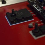
the paint underneath the mosfets has been removed it is just the pad covering it, I didn't use any power tools to make sure the surface is flat (took me an hour and half ...).
I used paste this time as a desperate attempt to make sure I have full contact between the surfaces, didn't use it before as you see in the pic, also before that piece of aluminum I used 3/4" fender washer but changed it last minute just to make sure i have same force clamping it down all over.
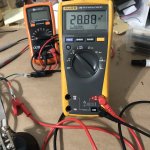
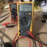
also the +/- voltage is the same as you can see in attached pics
I just ordered a thermometer and it will be here next few days, just to measure the temperature differences, I think at this point I have to take an step back and re do VGNS/VGSP measuring and biasing. I m doing electronics and building amps and stuff as hobby for last 20 years and i lost count of how many stuff I built and never felt this dumb) haha. it is usually something so simple that you over look.
I ll report back.
Thanks
A.
the paint underneath the mosfets has been removed it is just the pad covering it, I didn't use any power tools to make sure the surface is flat (took me an hour and half ...).
I used paste this time as a desperate attempt to make sure I have full contact between the surfaces, didn't use it before as you see in the pic, also before that piece of aluminum I used 3/4" fender washer but changed it last minute just to make sure i have same force clamping it down all over.
also the +/- voltage is the same as you can see in attached pics
I just ordered a thermometer and it will be here next few days, just to measure the temperature differences, I think at this point I have to take an step back and re do VGNS/VGSP measuring and biasing. I m doing electronics and building amps and stuff as hobby for last 20 years and i lost count of how many stuff I built and never felt this dumb
) haha. it is usually something so simple that you over look.I ll report back.
Thanks
A.
Attachments
Atto,
Follow this procedure:
To adjust the bias (50mV) and have 0mV as close as output offset it is necessary:
- Place a multimeter on the output that will allow you to see the offset.
- Place the second multimeter between TP4 and V- or between TP2 and V +.
Explanation:
- If you chose TP4 and V- you set P1 very little to increase the bias and then you set P2 to decrease the offset.
- If you chose TP2 and V + you set P2 very little to increase the bias and then you set P1 to decrease the offset.
In fact you increase the current and you go down the offset by touching both trimmer without moving the multimeters.
------------
Do this for your setting:
- Put a multimeter on the output.
- Put the second multimeter between TP4 and V-
You will not move these two multimeters during the settings
- Set P1 a little to increase the bias (do not go to 50mV again), and set P2 to lower the offset (P2 increases the bias of the other mosfet).
- You touch one after the other P1 and then P2 until the display of 50mV on a multimeter and 0mV ~ on the other multimeter.
This way you have your balanced bias on both mosfets.
sorry for late reply,
I finally got some time to do as ggetzoff suggested, also got my thermometer !
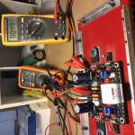
I changed the power supply design a little bit, now both channels are identical +/- 28v, also I removed the thermal paste underneath M1 and M2 and changed the pads to the new ones and replace the aluminum pieces to 3/4 fender washers, I removed the pads under M3 and M4 and added some thermal paste as Fab suggested.
Test process:
it took about 30 minutes for the offset and bias to finally become stable meanwhile it was changing constantly.
after 30 minutes I finally got it at 2.5-3mv offset with bias of 49-50mv. it changes up and down a little but not drastic like before.
I also measured the temperatures, M1 still get fast pretty quick after 20 minutes it was about 160 F !!! but after that it stayed at that temperature. M2 took longer to heat up, after 30 minutes it reached 120. the heatsink close to M1 was at 140 and close to M2 was at 113, so the thermal transfer is working.
I still fill like 160F w no load is pretty hot
I finally got some time to do as ggetzoff suggested, also got my thermometer !
I changed the power supply design a little bit, now both channels are identical +/- 28v, also I removed the thermal paste underneath M1 and M2 and changed the pads to the new ones and replace the aluminum pieces to 3/4 fender washers, I removed the pads under M3 and M4 and added some thermal paste as Fab suggested.
Test process:
it took about 30 minutes for the offset and bias to finally become stable meanwhile it was changing constantly.
after 30 minutes I finally got it at 2.5-3mv offset with bias of 49-50mv. it changes up and down a little but not drastic like before.
I also measured the temperatures, M1 still get fast pretty quick after 20 minutes it was about 160 F !!! but after that it stayed at that temperature. M2 took longer to heat up, after 30 minutes it reached 120. the heatsink close to M1 was at 140 and close to M2 was at 113, so the thermal transfer is working.
I still fill like 160F w no load is pretty hot
Attachments
Hi Aatto,
Your DC offset should settle quickly and drift slowly over time. It shouldn't normally bounce around, but rather exhibit a trend at the most. There shouldn't be a large change either.
Normally you would match beta and then tie the transistors together thermally. Heat shrink tubing works well with a touch of heat sink grease between the two parts. One critical thing about matching transistors is that they are extremely temperature sensitive. They must be at exactly the same temperature in order to measure beta close enough to match. I designed a jig that allows you to put a pair in and see if they match closely. Presort with the beta tester, then select pairs from that and use the jig. Basically it's just a diff pair (devices you are testing) with a current source for tail current. The collector resistors were purchased with a tolerance better than 0.1%. 100R0 from Digikey or Mouser would be fine. All you do is measure the voltage difference between the collectors. The lower the number, the better the match is.
Can you post the schematic you're working from? I'll have a peek.
-Chris
Hi anatech
it did stop changing after 30 minutes (going between 2.5 to 3.5mv back and forth) but yes before that it was changing constantly without me touching anything.
so you think that is one of my problems ? fab manual didn't say anything about matching input Qs
See this section of manual for matching of input transistors:
------
8.5.2.1
Measure HFE of transistors (optional)
Place higher HFE transistors in Q1 and Q2 position; Match Q1 with Q2 (<= 30%) Match Q3 with Q4 (<=50%)
-------
When you adjust DC offset with 2 pots like that and 2 thermistors it is normal that it takes a long time to stabilize the first time because we have a tendency to turn the pots too fast and we may be far away from the proper final setting. So the first time it is kind of more difficult to adjust. The perfect adjustment comes after 2 or 3 times of power up doing very fine tuning changes each time based on previous adjustment.
However, this does not explain the temperature difference. You have 20F difference between heatsink and M1 (160F-140F) so this is not good.... For M2 you have a small temperature difference which is ok. In fact, the temperature difference makes it difficult to adjust bias.
You have to ensure you have same current drawn from both positive and negative supplies. I would not trust anymore the 0,05 ohms source resistors and use an ammeter directly on each supply (or use another very small value resistors in series with each supply to measure voltage) to ensure you have the same current. Also, verify that both supplies voltage have the same values.
You should provide your measured values for each section of the manual requesting measurement so we can all verify for you if everything was done correctly.
Another thing to check is that the Mosfet input protection diodes (Zener and signal diodes) are not miexd up and properly oriented as per marking on pcb.
This amplifier have been built many times before and no issues was found.
Good luck
Fab
Last edited:
Hi Aatto
You may also investigate thermistor TH1 since if failed it would explain the behaviour you are seeing for M1 excessive temperature since it is depending on M3 VGS which is depending on proper TH1 behaviour. Normally the voltage across TH1 should vary with heatsink temperature. Ensure TH1 is either in contact with heatsink or very close to like 1mm away. You can compare with TH2 behaviour.
Fab
thank you Chris, I will use this if I have to redo the thing, at this point I m hoping it is somewhere else so I do not have to redo the componentsHi Aatto,
Your DC offset should settle quickly and drift slowly over time. It shouldn't normally bounce around, but rather exhibit a trend at the most. There shouldn't be a large change either.
Normally you would match beta and then tie the transistors together thermally. Heat shrink tubing works well with a touch of heat sink grease between the two parts. One critical thing about matching transistors is that they are extremely temperature sensitive. They must be at exactly the same temperature in order to measure beta close enough to match. I designed a jig that allows you to put a pair in and see if they match closely. Presort with the beta tester, then select pairs from that and use the jig. Basically it's just a diff pair (devices you are testing) with a current source for tail current. The collector resistors were purchased with a tolerance better than 0.1%. 100R0 from Digikey or Mouser would be fine. All you do is measure the voltage difference between the collectors. The lower the number, the better the match is.
Can you post the schematic you're working from? I'll have a peek.
-Chris
and I m using the schematic posted in POST#4
Thanks
A.
It seems to me that in the photo the GND is not connected (only the PGND) and suddenly the input stage and the CCS are not connected to the GND via R27.
Maybe the picture is misleading.
GND and PGND is connected w a wire soldered to the post, did it since I couldn't find find all my alligators during VGSN/VGSP measurement.
Also, potentially the paint under the thermistor can give wrong reading due to poor heat transfer of the paint surface?
that is a good point, will remove the paint
Thanks.
Last edited:
It is effectivemment possible according to the thickness of the painting which can make barrier.Also, potentially the paint under the thermistor can give wrong reading due to poor heat transfer of the paint surface?
Personally I did not have any particular problem with the thermistors that do not touch the heatsinks and the temperature rise of the mosfets is almost identical on M1 and M2 to finish stabilizing to 41° on the heatsink.
See this section of manual for matching of input transistors:
------
8.5.2.1
Measure HFE of transistors (optional)
Place higher HFE transistors in Q1 and Q2 position; Match Q1 with Q2 (<= 30%) Match Q3 with Q4 (<=50%)
-------
When you adjust DC offset with 2 pots like that and 2 thermistors it is normal that it takes a long time to stabilize the first time because we have a tendency to turn the pots too fast and we may be far away from the proper final setting. So the first time it is kind of more difficult to adjust. The perfect adjustment comes after 2 or 3 times of power up doing very fine tuning changes each time based on previous adjustment.
However, this does not explain the temperature difference. You have 20F difference between heatsink and M1 (160F-140F) so this is not good.... For M2 you have a small temperature difference which is ok. In fact, the temperature difference makes it difficult to adjust bias.
You have to ensure you have same current drawn from both positive and negative supplies. I would not trust anymore the 0,05 ohms source resistors and use an ammeter directly on each supply (or use another very small value resistors in series with each supply to measure voltage) to ensure you have the same current. Also, verify that both supplies voltage have the same values.
You should provide your measured values for each section of the manual requesting measurement so we can all verify for you if everything was done correctly.
Another thing to check is that the Mosfet input protection diodes (Zener and signal diodes) are not miexd up and properly oriented as per marking on pcb.
This amplifier have been built many times before and no issues was found.
Good luck
Fab
Hi Aatto
You may also investigate thermistor TH1 since if failed it would explain the behaviour you are seeing for M1 excessive temperature since it is depending on M3 VGS which is depending on proper TH1 behaviour. Normally the voltage across TH1 should vary with heatsink temperature. Ensure TH1 is either in contact with heatsink or very close to like 1mm away. You can compare with TH2 behaviour.
Fab
Fab I have no doubt that I did a mistake somewhere and it is not your amp.
the voltage of PS is identical, I did not yet measure how many amps it draws but I can do that.
Thermistors are touching the surface of the heatsink but as pinnocchio suggested it might be the paint causing an issue here, I will remove that tonight. hopefully I don't have a faulty thermistor
I did adjust the second board last night as well. the bias and offset stabled faster than the first board, after 10-15 minutes it stopped moving but the temperatures are almost identical with the first board (160F for M1 and 120 for M2).
I ll recheck the components and will report back.
PS. as for my measuring process I have pics and will post them when I got home
Hi All,
Here is some information for the transistor beta matcher. I'm going to try and link to the post, but it is #235 in case this doesn't work properly. You are welcome to build it, and a few members have successfully designed their own boards for it. Ignore the one with a fan. You really don't want to do that. I gifted this to the DIYAudio community, so it is free to build and use. cogeniac built a nice board that I have tested. He may have the gerbers that you can use to order a board with. The boards I made were done with the toner transfer method, so all you need is the PDF file for the PCB.
Beta matcher
You can easily match pairs to within 1% with this jig and you don't need an expensive meter to use it. You will be measuring less than 1 mV with very tightly matched transistors. Also, once you have a pair matched that tightly, you have to match the degeneration resistors if they are used. If not, they can throw your match out. Use 1% metal film resistors for these. Degeneration resistors are located in the emitters of a differential pair.
Best, Chris
Hi
Update: so I removed a little more paint around M1 and M2 also removed the paint under thermistors and whola ! it made a huge difference. both M1 and M2 have the same temperature around 140-147F after 20 minutes and the heatsink is around 125-135F, also the heat is much more uniform and steady across the whole heatsink.
Bias wise i get steady 49mv with offset of ~0.8mv, it is almost stable after 10-15 minutes (may change back and forth between 0 and 1mv) I have almost identical results between both boards, the first board tho is much more sensitive while turning p1/p2, slightest touch and it jumps up and down but at this point it is stable with same numbers
so i guess the whole problem was the thick paint under thermistors.
I ll play around more and will report back, after a few more time adjusting the bias i ll let the amp burn in for a few hours.
thank you everybody
Update: so I removed a little more paint around M1 and M2 also removed the paint under thermistors and whola ! it made a huge difference. both M1 and M2 have the same temperature around 140-147F after 20 minutes and the heatsink is around 125-135F, also the heat is much more uniform and steady across the whole heatsink.
Bias wise i get steady 49mv with offset of ~0.8mv, it is almost stable after 10-15 minutes (may change back and forth between 0 and 1mv)
I have almost identical results between both boards, the first board tho is much more sensitive while turning p1/p2, slightest touch and it jumps up and down but at this point it is stable with same numbers so i guess the whole problem was the thick paint under thermistors.
I ll play around more and will report back, after a few more time adjusting the bias i ll let the amp burn in for a few hours.
thank you everybody
- Home
- Amplifiers
- Solid State
- USSA-5 Build with Review