Question...
Build the 2 channels, tested and mounted one of them on the heatsink.
All OK (except I dropped Cz on the floor and can't find it...), I am up to the Rv calculation point.
Regarding front end bias of 20mA; Can I go a little higher to say 32mA? will it benefit?
In my VFET2 Pass amps Nelson used 1.5V ... 1.8V/47R5 = 32 ... 38mA
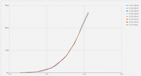
I included my Id") / Vgs (x) measurements of the mosfets 2sk2013_N/2sj313_P
/ Vgs (x) measurements of the mosfets 2sk2013_N/2sj313_P
I am very curious to the sound, will take a couple of days ....
Build the 2 channels, tested and mounted one of them on the heatsink.
All OK (except I dropped Cz on the floor and can't find it...), I am up to the Rv calculation point.
Regarding front end bias of 20mA; Can I go a little higher to say 32mA? will it benefit?
In my VFET2 Pass amps Nelson used 1.5V ... 1.8V/47R5 = 32 ... 38mA
I included my Id
/ Vgs (x) measurements of the mosfets 2sk2013_N/2sj313_PI am very curious to the sound, will take a couple of days ....
Attachments
Hello asanden
I believe that the 20mA is given for 1A bias, personally I adjusted to 23mA for just over 1A, namely that all adjustments are carefully established by FAB;
I am not sure that it is beneficial and only Fab can give you a correct answer but currently he is on vacation and not sure that you will have a quick answer.
ID of mosfet driver
Hello Asanden and thanks Project16
I got a few minutes so:
Regarding the drain (or source) current of these mosfet you are correct that 32ma is more in the linear region of the curve. My only concern may be the drive current to be provided by the bjt input stage. For the ussa-3 with input jfets I suggest about 27ma. Since I got good sound results with 23-25ma (for final output bias) with ussa-5 I have not tried to push the mosfet driver current higher. The main reason is that my prototype pcb used small heatsinks for drivers (thus power dissipation issue) instead of the main big heatsink. Now with the dedicated pcb then it is no more a problem.
I would not be concerned about close to 30ma but higher than that he THD may be affected a bit in a certain way, if that matters to you...
I suggest you try first with below 30ma (at final bias) and then try with a higher value for comparison on sound. And of course report your findings.
Fab
I installed the RV resistors and finally got some free time to play tonight, after re adjusting P1 and P2 to to have >5mv DC offset I have 50-52mv across R15 or R16 on both boards but one of the transistors (M1) get significantly hotter than the other one, is this normal ?
the Bias looks fine (50mv across R15/16) but I ll do more measurements later on, all pads are same size and type and I also used thermal paste sandwiched between, the weird thing is both boards behave the same, M1 gets hot way faster and way more, I ll try to get my hands on a thermometer and will do more measurements hopefully tonight . Thanks.
. Thanks.If you have DC offset minimized then you have same current in both mosfet M1 and M2 (or measure voltage across source resistors). Since you also have same voltage (positive and negative) then you have same power to dissipate in both mosfet. If temperature is different then it is heat transfer that is different. Otherwise it would mean very different RDSon value between N and P channels. The mosfet case temperature should be only a few degrees over the surrounding Heatsink temperature if you have proper thermal contact. Mosfet positions (N and P) should be about the same on Heatsinks.
Faster or slower heating is not important, just check after stabilization. The mosfet drivers differences will be eventually compensated by the thermistors effect.
Fab
Faster or slower heating is not important, just check after stabilization. The mosfet drivers differences will be eventually compensated by the thermistors effect.
Fab
Last edited:
Thanks Fab, from what you said I must have heat transfer problem, I have been using the same pad for other amps as well and never had a problem, and as you said the temperature difference from the M1 case and heatsink itself is way different too, the only thing that comes to mind is it might be a thick powder coated area and that interfere with heat transfer, I will remove the paint underneath the mosfets and we'll see how it goes, but I will do more measuring before that to double check if I have everything correct before starting to remove the paint.
Thanks.
Edit: is it enough for thermistors just to touch the heatsink or I need better connection ? some thermal paste maybe ?
Thanks.
Edit: is it enough for thermistors just to touch the heatsink or I need better connection ? some thermal paste maybe ?
Last edited:
hey ggetzoff. sorry was working this weekend.
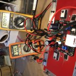
well, yes and no, I still have the same issue, the voltage across both R15 or R16 is the same and it reads between 50mv to 55mv and DC offset is about 3-5mv as you can see in the pic but my m1 mosfet get significantly hotter than the other one, much hotter ! m2 is getting warm and easy to touch but m1 get hot fast and it will burn you if you hold your finger more than 2 seconds, I removed the paint underneath all the mosefets, and the heatsink get actually warmer than before but same problem still exist.
any suggestions ? can i do all the measurements again from scratch ? or I have to remove components, just can't wait to hear this amp
Edit: same issue on both boards, I have seen this problem before and it always happen just after you put the amp together and before adjusting the bias, like one mosfet is running on significantly higher bias, but even with none matched mosfets it should not be that much difference between M1 and M2 temperature. so what do I do ? :\
Attachments
Last edited:
Hi Aatto
Be assured that you have the same power to dissipate in N and P output mosfet if dc offset is close to 0 Vdc. Matching has no influence between N and P channels. Matching is for equal current sharing of same polarity. The dual die mosfet for same polarity ensures best matching since in same package.
Just to be clear the difference in temperature you get has nothing to do with the design and you would get the same for other amps. This is a thermal interface issue.
From the picture I see some things to look at:
1) thermal pads do not require thermal grease and you seem to have put a lot...this may create variation between the 2 mosfets.
2) you seem to still have paint and it may not be uniformed. If you remove it must be extremely well leveled to not have any bumps...
3) the cut aluminium part between screw and mosfet could be replaced by a big washer having an uniformed surface.
In the end I would consider <=5 degree difference between N and P mosfet quite acceptable.
Good luck.
Fab
Last edited:
- Home
- Amplifiers
- Solid State
- USSA-5 Build with Review