A lot of good people run away when presented to this little problem....people with degrees told that "no time enough"..... others told me they will answer me later on(never done).....some friends told me that the situation has "no solution".... this is the easier way.
I cannot, but some "golden electronics monsters", related to knowledge, will think that's easy!
But i will give a gift to the challenging one that helped me.... an magnificent problem that you will spend at least 30 minutes thinking if you are a very high Intelectual Quocient.... some people is trying since the 1995!
Carlos
Attachments

Re: Where is the problem?
Maybe that's why he could never get a answer!
Elso Kwak said:
I don't see any problem presented.
Maybe that's why he could never get a answer!
Re: Re: Where is the problem?
Hi Bill,
OK problem solved!
You may have the gift.
Bill Fitzpatrick said:
Maybe that's why he could never get a answer!
Hi Bill,
OK problem solved!
You may have the gift.
Keld said:The answer is 42!
Fool. The answer isn't a number - it's a color. Maybe red.
If you want to know the relative current gain for each of the darling ton sets than that is a fairly easy question, the first one will be around 3000, the second 4875. Of course this will depend also on the bleeder resistors a little (but not a lot), and the rather large range of values you will have for the real life trasistors.
But then, this may also nt be an answer to the question you were asking (although it is an answer to A question).
But then, this may also nt be an answer to the question you were asking (although it is an answer to A question).
The answer is to make sure that the circuit they are used in is immune to variations in transistor gain. The "N" and "P" types will always be different at some point, as you have seen. If you built another one, then the gains will be different again. Make it irrelevant. Making R1 & R2 the same in each one will help swamp the differences.
Now you have another answer. What was the question again?
Now you have another answer. What was the question again?
Answering all. if you are not a gênius..
Of course is the way a find to challenge someone to help me... i do not know the result... this is a problem to me.
Elso, I suppose different resultant gain will make a mass in the resultant audio.. that's what i want to know... thank you
Bill Fritzpatriot...take a look under the place you sit, you maybe smash some good friend, sorry, i imagine you cannot hold the gift.
Keld, thanks your number 42... i will think about that.
Bill Fritzpatriot... reference the fool... let me remember that you making some confusion between my person and your President or the image you see when shave yourself in the morning... do you shave?
Chris Ma... thats the best answer i had for a while, congratulations, you are inteligent and normal, some others could reach one point in the scale (unfortunattely was a decimal point)
Big parnsnip.... sorry be the English, we talk portuguese in this country.... take a look in the map.... a big inverted triangle in South America.... space to receive almost 40 England and all surrounded Islands.... I am trying to find James Mergulhão Green, my lost cousin ... can you help some?... he is in England, his father work for Xerox and came hear to construct a maintenance center in our Capital.... unfortunattelly he fail and return and stollen my cousin.
Johnnyx... i suppose you are correct, but not entirely precise the way i need.... asking formula to match them changing resistor...if possible... i am not sure....but, was kind.... thanks to be educated the second time i am visiting you all friends.
The others, if want to fight or make troubles.... please... go to this new Vietnam we are starting to see.
Destroyer X is a kind person that normally puts some "good people" upside down like fruits in the coconut trees.... a thin horizontal cut with knife and let them cook with sun heat... fritzpatriot will be a very good cookie hahahaha!
Destroyer X
If you have not a good word to spoke.... better not to try.
Ok, if you think about it a bit like this:
when the trasistors are turned on, there will be about 0.7V between the base and emitter, so there will in turn be about 0.7V accross the resistos, and so you will get a current folw of 0.7/R through the resistor.
if you want to know what effect this has on the second trasistors curent gain, you will need to know how much curent if flowing from the emiter, and hence the input current.
if you know the input curent needed for a specific output curent, you can then decrease the value of R2 to the point where the total output curent from the first transitor will be the curent flowing into the resistor and base of the second transistor. so if you have half the curent through the resistor you will have roughly decreaced the curent gain by a factor of two.
however, this change will not stay constant over the whole spectrum out output curents, and so probably doesn't have much real use at all.
(any closer?)
Member
Joined 2004
I always try to match transistors. Small signal transistors are easier to match, since they are not as expensive as power transistors, so therefore you can buy a bunch (50-100 and even get a discount) . To do the same with power transistors can be expensive, but always buy some extra, I say, simply because then you have spares.
In my experience both BD139 and BD140 have a HFE of around 100 and 2N3055 and MJ2955 have around 50. Are you sure about the specifications given in your picture, destroyerx?
Now about the resistors: According to "The Art of Electronics" by Horowitz and Hill the resistors, the ones across the B-E on the power transistor, are there to make sure, that the driver transistor can turn off the power transistor quickly enough. Otherwise the Darlington will act as a slow transistor. The resistor across the B-E in the driver transistor is not mentioned in the book, so I therefore conclude that it is not nessecary unless you have an extra transistor (3 step). The 150 ohm resistor matches the info in the book, but if the 4K7 resistor is needed, it should only be "a few thousand ohms" (my interpretation: 2K).
You also ask for a formula for gain. The current gain is to multiply the two gains ( more correctly named HFE). The voltage gain is 1.
How long can you enter a football field? One step - then it is entered.
How long can you walk into a football field? To the middle - then you walk out again.
I don't know the rope one, but the english in that sentence is for me a bit hard to understand.
. To do the same with power transistors can be expensive, but always buy some extra, I say, simply because then you have spares.In my experience both BD139 and BD140 have a HFE of around 100 and 2N3055 and MJ2955 have around 50. Are you sure about the specifications given in your picture, destroyerx?
Now about the resistors: According to "The Art of Electronics" by Horowitz and Hill the resistors, the ones across the B-E on the power transistor, are there to make sure, that the driver transistor can turn off the power transistor quickly enough. Otherwise the Darlington will act as a slow transistor. The resistor across the B-E in the driver transistor is not mentioned in the book, so I therefore conclude that it is not nessecary unless you have an extra transistor (3 step). The 150 ohm resistor matches the info in the book, but if the 4K7 resistor is needed, it should only be "a few thousand ohms" (my interpretation: 2K).
You also ask for a formula for gain. The current gain is to multiply the two gains ( more correctly named HFE). The voltage gain is 1.
How long can you enter a football field? One step - then it is entered.
How long can you walk into a football field? To the middle - then you walk out again.
I don't know the rope one, but the english in that sentence is for me a bit hard to understand.
Bwuahahahahaaa........
The thread should be "If you're a genius, please put a question and its answer"
A lot of good people run away when presented to this little problem....people with degrees told that "no time enough"..... others told me they will answer me later on(never done).....some friends told me that the situation has "no solution".... this is the easier way.
I don't see any problem presented
Maybe that's why he could never get a answer!
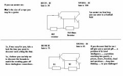
R1=150 R2=4K7
But then, this may also nt be an answer to the question you were asking (although it is an answer to A question).
Now you have another answer. What was the question again?
Bill Fritzpatriot...
(any closer?)
The thread should be "If you're a genius, please put a question and its answer"
By adjusting R1 and R2 you can match the working point of both darlingtons to be the same but you will never be able to match the DC current gain of both darlingtons for more than a single output current value at the same time. Additional resistors are required in order to accomplish that
Thank both of you Eva and lumanauw
I assemble and making those changes i could match them.... VBE error not more than 20 percent.
But audio was mufled.... without brightness and the bass shows something like decay.... short time bass..... a fast lowering voltage supply or something alike..... I used good Sanken transistors 2sc2292 excited with BD139.
I decide to buy real darlingtons.... TIP142 and TIP146.... now the bass appear punchy and long the way i like.... also the highs are OK in comparison the original circuit from Sony TA-F30..... an old and ugly amplifier.
Trying to compensate here and there i feel that i was constructing a "Frankstein darlington".... so, why not to change mi mind into real series darlington?
Thank you by your interest and Kindness.
Eva, my wife is from Spain...... she has documents from Spain.... family Rapela, from Orenz Barbadanes descendent.
Lumanauw.... i was thinking how to pronunciate your name....can i use m in the place of the terminating "w"?
regards
Carlos is de Destroyer X.... burning components .... extra burner!
Yeah!
And all this lengh and width is twice its half part..... its three times its third part.......multiplied buy 10004657 and the result of this multiplication divided by 10004657 will be the value you will find everytime, everywhere and for all the measures.
thanks
Thats good.....but not enough
Carlos
And all this lengh and width is twice its half part..... its three times its third part.......multiplied buy 10004657 and the result of this multiplication divided by 10004657 will be the value you will find everytime, everywhere and for all the measures.
thanks
Thats good.....but not enough
Carlos
- Status
- This old topic is closed. If you want to reopen this topic, contact a moderator using the "Report Post" button.
- Home
- Amplifiers
- Solid State
- If you're not a gênius do not read that..jump!