I have set the quiescent current to .5 amp and the transistors run cool. By cool I mean you can touch them for 5-10 seconds without any discomfort.
The aluminium profile is a 4mm sheet. And I have put heatsink paste between the aluminium angles and the tunnel heatsink.
The transistors did get very hot when the qs current was increased beyond 1 amp. So I settled for half the value.
The fan is a 12v fan but to eliminate fan noise I am running it at 9v.
The amp still sounds good and the heat is substantially reduced.


Computer CPU paste ("Arctic" ... etc) works better for metal-on-metal work imho....
The aluminium profile is a 4mm sheet. And I have put heatsink paste between the aluminium angles and the tunnel heatsink.
...
Ok guys - I have not built this kind of amplifier before so finding it a steep learning curve.
I am using surplus components that I have here lying around (I am a Radio Amateur - so have a large junk box lol).
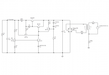
Below are the circuits I am using for the smoothing circuit and JLH amplifier.
The transformer I am using is out of a 3A bench PSU (details unknown).
I am using a 22V AC secondary for each side. Each secondary winding is feeding a bridge rectifier.
I am wanting to test the Power Supply and get this working before building the amplifier.
Can anyone explain to me how this smoothing circuit works as I was expecting the output to be 31V (as i multiplied 22V by 1.414) But I am finding the voltage is a lot higher than this.
I switched the supply off when the output climbed above 38V as I was wary that my capacitors are only rated at 50V so didnt want to damage them.
I thought this maybe because I wasn't loading the output of the supply (as would be the case if the amplifier was attached). Even varying the potentiometer didn't trim the voltage.
So my other question is what load resistor do I need across the output of the power supply to simulate the amplifier?
I have tried a 47K 2W resistor but this gave the results above. Do I need a lower value?
Thanks in advance
Nigel
I am using surplus components that I have here lying around (I am a Radio Amateur - so have a large junk box lol).
Below are the circuits I am using for the smoothing circuit and JLH amplifier.
The transformer I am using is out of a 3A bench PSU (details unknown).
I am using a 22V AC secondary for each side. Each secondary winding is feeding a bridge rectifier.
I am wanting to test the Power Supply and get this working before building the amplifier.
Can anyone explain to me how this smoothing circuit works as I was expecting the output to be 31V (as i multiplied 22V by 1.414) But I am finding the voltage is a lot higher than this.
I switched the supply off when the output climbed above 38V as I was wary that my capacitors are only rated at 50V so didnt want to damage them.
I thought this maybe because I wasn't loading the output of the supply (as would be the case if the amplifier was attached). Even varying the potentiometer didn't trim the voltage.
So my other question is what load resistor do I need across the output of the power supply to simulate the amplifier?
I have tried a 47K 2W resistor but this gave the results above. Do I need a lower value?
Thanks in advance
Nigel
Attachments
If a nominally 22V secondary gives over 38V DC then something is not as you think it is. Double check everything. If you haven't already done so, build and use a lamp limiter.
If you work out the current drawn by a 47K resistor you will realise why it won't help you test the supply.
If you work out the current drawn by a 47K resistor you will realise why it won't help you test the supply.
It could be unloaded rating. Transformers have to be designed with the actual load in mind. If it is 90% efficient that represents 10% losses. That is lost in winding resistances and power in the iron core (B-H losses). You could check the resistances of the windings and estimate the losses at full load, and see if that accounts for the voltage increase.
You might also check the magnetisation current (primary current with no load) - carefully as this involves hooking up an ac ammeter in the mains side (or a sensitive current clamp). If the transformer is being overdriven (too low a voltage for UK mains which are still really "240V") the current might be high. My estimate is that the current should be less than 10% of full load, but would ideally be less than 5%.
As a quick check: what is the AC voltage of the secondary with no rectifier attached? Check the transformer first, in other words. If this is less than 30V your capacitors should not reach 50V.
The power supply by the way is a "capacitance multiplier" and only provides smoothing, not regulation.
...another way to measure the magnetisation current is to wire up a 1 ohm power resistor in series, with one end connected to neutral. Then measure the AC voltage across it. That's probably a safer approach, but you might need a sensitive AC meter as the voltage should be low (magnetising currents about 10mA might be possible if the unit were rated at 22Vx2x3A=132W (VA) but ought to be more like 4-5A (150VA+) if 3A output were continuous DC.
Last edited:
Ok guys - I feel stupid now.
It was my mistake - I thought my primary winding was 22V (11V + 11V windings in series) but in fact it was 27V (11V + 16V windings in series). So 27 x 1.414 gives 38.1V and I am getting 37V - which is correct.
Its because I wired the transformer a few weeks ago and had it in my head that my secondary was 22V - Duh - not to self - Check next time.
I am now going to change it to 21.5V secondary (using a 16V + 5.5V winding in series) which will give me 21.5V - So 21.5 x 1.414 = 30.4V. I am hoping this will be OK to power the JLH amplifier.
I am interested though what the potentiometer does on the capacitance multiplier (bottom circuit on my diagram above )as it does not change the voltage when turned - Is this to control the current?
Nigel
The power supply smooths the ripple voltage. As it does not regulate, the output voltage depends on the load current. At low currents the voltage will pretty much rise to the main feed-in voltage. But if you power up your amp with the supply, the pot should control the voltage indirectly by limiting the base current to the transistors.
Most PSU's regulate and I would recommend a regulated PSU rather than a capacitor multiplier. Particularly prone to short circuits when the cap on the base of the BD139 could discharge through it and the 2N3055, killing both.. Only a few extra parts needed to change to a regulated PSU.
Most PSU's regulate and I would recommend a regulated PSU rather than a capacitor multiplier. Particularly prone to short circuits when the cap on the base of the BD139 could discharge through it and the 2N3055, killing both.. Only a few extra parts needed to change to a regulated PSU.
Last edited:
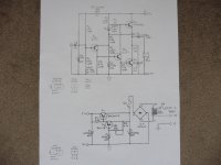
Here's a classic.
Bias resistors are replaced by a constant current source as that is more efficient.
OPtional current limiting transistor (Tr4).
Parts are set up for single channel.
Mains transformer side has estimated winding impedances to check droop. Note that open circuit voltage needs to be about 32V, but could be lower if the actual resistances of your windings are lower. Peak DC (no load) will rise to about 48V!
At 1.25A output the supply drops to about 33V D.C. so there is only about 5V across the 2N3055. You could experiment with your transformer tappings to achieve 27V supply output at the load, with about 33V on the 2N3055 collector. Are you planning to use one PSU for two channels?
If so then the transformer needs to be a little higher voltage or even lower impedance, and the short circuit protection resistor reduced to 0.1 ohms, but the transistor will get hot unless also on a large heatsink.
Probably best to run one PSU per channel, but expensive.
Attachments
- Status
- This old topic is closed. If you want to reopen this topic, contact a moderator using the "Report Post" button.
- Home
- Amplifiers
- Solid State
- JLH amp voltage drop