Hi Anton,
Your file now showing V(D2) as visibly clean, I'd say you can't hear any distortion from this.
Weighted THD 0.27%. It's safely below my suggested 1% threshold for audibility.
The weighted THD FFT looks good too.


I added the double differentiator from Post 10 circuit (eg F6 Copy/Paste). Added a bufer because of your high 4k7 load. Added Av from Vout/Vin (4.7V/1V), then mached D2 for about the same peak as Vout.
BTW you used square brackets rather than curly ones.
You might be the first one to use this method apart from me.
Cheers, IanH
Your file now showing V(D2) as visibly clean, I'd say you can't hear any distortion from this.
Weighted THD 0.27%. It's safely below my suggested 1% threshold for audibility.
The weighted THD FFT looks good too.
I added the double differentiator from Post 10 circuit (eg F6 Copy/Paste). Added a bufer because of your high 4k7 load. Added Av from Vout/Vin (4.7V/1V), then mached D2 for about the same peak as Vout.
BTW you used square brackets rather than curly ones.
You might be the first one to use this method apart from me.
Cheers, IanH
Attachments
Thank you Ian for your post. Your insights, analyses and the enhancement of the [CSPR] schematic are highly valuable and valued.
I am simulating a resultant Class aP amplifier based on the above. I will post its schematic and .asc file per your additional request for FFT and D2 analyses.
Best
Anton
I am simulating a resultant Class aP amplifier based on the above. I will post its schematic and .asc file per your additional request for FFT and D2 analyses.
Best
Anton
. Antoinel's Class-aP (Post 5) would seem to fit into this category if the switching rate is fast enough. I'd be interested to see FFT plots and some D2 values for any of Antoinel's Class-aP amps.
Cheers
Hello Ian, and All,
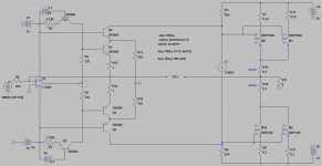
Please find attached the schematic for a simulated Class aP amp per your request above. Please note:
1. I am using a complementary symmetry precision rectifier [CSPR] using switching BJTs instead of JFETs. Its rectified music signals [analog pulses] are clearly defined. I am also uneasy using JFETs like in the last post because they may operate in enhancement mode.
2. The %THD at the output of the OpAmp [encircled] is a strong function of the idle current flowing through the switching BJTs. I adjust their bias to be Class AB with the encircled resistors of the constant current sources.
3. The power output stage is made of complementary symmetry Mosfets operating in common source configuration. They have different values of resistors at their sources and for their gate drive; because;
4. I use CSPR [as a convenient tool] to match the performance of the upper Mosfets to that of the lower Mosfets before applying overall negative feedback; so as to minimize [or attempt to] %THD. The outcome of this fine tuning are close values for idle and pulse currents across the [0.1] sense resistors. The pulse currents do not bottom out at zero.
5. The application of overall negative feedback using a [1K] resistor gives a THD = 0.03%.
The .asc file will follow.
Best
Anton
Attachments
Hi Ian,
My apology for the delay in posting the attached [.asc file] for the schematic of my previous post.
Best wishes. Anton
Hi Anton,
No worries. I was asleep then ... in Australia. Expect delays.
I don't know how you intend to implement the negative feedback part?
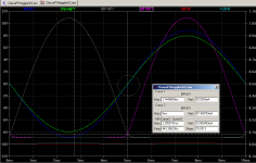
What I can show is how to analyse just the splitter. I have used an ideal linear output stage amplifying the splitter currents by 100 times.
Looking at the D2 waveform distortion is only just visible. Weighted THD of D2 is 0.7% (ideally we want 0.1% or slightly less to be on the safe side).
BTW your splitter stage biasing is very sensitive to R1 and R2 values. This highlights the need for some sort of Vbe temperature compensation because you want to keep the idle point fairly steady from at least 10C to 30C (50-85F) range.
Notice R17 and R18 can set the stay on current for non-switching in the output stage. So if the idle current from the splitter can be set less than the stay on current then the output stage idle current will be less sensitive to the splitter's idle current and it's temperature changes; which was/is the intent of the original Blomley.
----
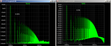
Notice the ordinary FFT plot show about -60dB/decade rolloff which is a highly desirable property for Class-B amplifiers because the high order harmonics cannot dominate giving the "Class-A sound" with Class-B.
-----
I guess you will be adding an input stage since driving into 100 ohms is rather low.
Your Class-aP circuit could be improved if the output stage is made more linear and less sensitive to temperature changes. It all depends on how much global feedback you use. If you don't want to use much global feedback then you need a more linear output stage than the one at present.
Cheers
Attachments
Hi Ian,
Thank you for your post which is rich in valuable guidance and know-how. First and foremost, I admire your evident high-level proficiency in both Electronics and LTSpice modelling. Commendable.
I'll gladly adopt your above points of advice. I'll further simulate the power output stage of Blomley which has high gain and is possibly more linear than the one I'm using.
Best wishes
Anton
Opening the Gap
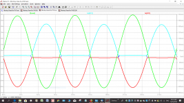
In the attachment which plots output current with 60 mV sine input I see a gap between the bottom line conduction in each circuit half and if the closest points are drawn then the middle conduction path looks like a square wave with sloping sides - with brief excursion blocks either side of 0 mA back and forth.
The red traces have greater magnitude than the blue ones - so if the result at the output looks symmetrical how much crunching has there been by the red trace signal and how has this affected the harmonic structure.
Attachments
Hi Anton,Hi Ian,
Thank you for your post which is rich in valuable guidance and know-how. First and foremost, I admire your evident high-level proficiency in both Electronics and LTSpice modelling. Commendable.
I'll gladly adopt your above points of advice. I'll further simulate the power output stage of Blomley which has high gain and is possibly more linear than the one I'm using.
Best wishes, Anton
Thanks for your kind words. I have been working on nonstandard typologies for about 20 years and started with Tina 4.
The Blomley used CFP type triple "sub-amp" because the power transistors then were quite slow and their beta's were useless for direct current drive from the splitters. Sure, have a go at his sub-amps using modern parts.
Attached is a CSD (current source driven) power stage as per Linear Audio Vol.13 amp using RET's. Modern RET's have a fairly constant Beta up to a few amps and in this configuration can be paralleled without emitter ballast resistors (base resistors instead).
The problem with direct current drive from the splitters has been turning them off fast, eg, for when using a 20kHz full swing test signal. With the help of a few on diyAudio a speed up circuit was developed and is included in the attached so cross-conduction can be mitigated to a safe level.
With two RET's in parallel you can safely get 100W for 8 ohms. Current limiting and basic SOA is provided by the base resistors. One of the benefits of CSD power stages is no Vbe biasing thermal feedback is needed. A thermal cutout can be used to reduce heatsink size and for shorts on the outputs.
With an extra opamp for NFB it gives 3ppm unweighted and 0.03% weighted (see attached). The extra opamp is for a demonstration only. I expect you will develop something more appropriate to suit your likes including some compensation.
Cheers
Attachments
Last edited:
Hello Ian and thank you for your above post which overflows with a generous dose of valuable knowledge, expertise and guidance.
The CSD power output stage in your [.asc file] is the one to use. In addition to the independent and proven results of your research, its resultant pulse currents are identical in magnitude for the upper and lower Pout half-stages. With the added bonus of a stay-on current [your term] once the pulse disappears. Meaning the output transistors do not turn off in operation This is a real accomplishment and a leap forward for improving this and other amps.
I'll buy the Linear Audio Vol. 13 which has your article on CSD. And also read-in the links at the bottom of your posts. There's a lot of education therein and in Linear Audio.
I have a suggestion which I hope that you consider; because of our intense interest, enthusiasm and evident skill in this subject matter and more. You've already done a lot of research towards the following suggested power amplifier, and I feel that you are having a lot of fun in this thread.
1. Take your Cube-Law Class A amplifier.
2. Remove the cube-law and linear drivers.
3. Plug-in a CSPR at the vacant location of the above drivers.
4. The valuable enhancements which precede and follow the CSPR driver stay.
5. The PCB for the Cube-Law Class A amp exists. An epi-board for CSPR can hopefully sit on top for the time being. That'll be a beautiful sight to see.
I will continue to look forward to your theoretical and practical output. This nonstandard topology [thanks to Blomley] is truly in evident great hands [yours]. I am glad for this open source diyAudio which continues to offer new possibilities for other amplifiers to happen.
Best wishes
Anton
There was a recent article on the Blomley over on 'allaboutcircuits'. Its a great read.
My 40-Year Love Affair with a Remarkable Amplifier—A Class B Amplifier for Audiophiles
I also did a sim for curiosity. You will need to put your own models into it and alter voltage source V1 to get the desired quiescent current:
Where do I find "discrete models.txt" required by this sim?
I got around this in Post 10 sim by adding:Where do I find "discrete models.txt" required by this sim?
.include Cordell-models.txt
.model 2N2955 ako:MJL21193C
and remove the ".inc discrete models.txt"
Unfortunately, the suggested solution is based on some erroneous assumptions. Whenever the dynamic (signal) energy level is in excess of the static (DC bias) energy level, there are two possible scenarios: either switching to higher static (DC bias) energy level or remaining in saturation (nonconducting state).
Hugh, thank you and...
please accept my apology for the time taken in responding to your post.
Part of the delay is due to the Summer holiday season here in Northern parts. The remainder arising entirely from those difficulties attendant to providing accurate and meaningful responses to your excellent points and questions.
...(1) In each of my two earlier posts, only the first FFT is from the non switching version. The second is provided merely for comparison. i.e. the same output stage but without the non switching circuitry in operation. Also, I wouldn't read too much into the absolute shape of the mathematical noise floor as this is quite mutable over wide ranges of various input parameters.
...(2) I am most grateful for the considered emphases you have made in this part of your response and confident that you are quite correct in these assertions. To me, the most significant of your points here being that, perceptually, there exists a substantive decoupling of harmonic profile from absolute distortion level. I remain very keen to develop a clearer understanding of how this may apply in its limits. Particularly in the light of Ian's response above, do you have any thoughts on an outline numerical framework for this?
...(3) I accept your first point here without reservation and concur with your very reasonable expecatation. It is both disappointing and at first somewhat puzzling that this clearly does not apply. I will conjecture below as to why this may be so. Further by inference it is also accepted that some moderately uniform predominance of even over odd harmonics may well be preferable to a listener. Although again, at present, I have no clear insight as to any numerical basis for this. I would be most grateful to learn of any thoughts you may have on this matter.
...(4) Having worked to investigate your first question here, my current conclusion is that whilst global NFB is certainly an important factor it may not be the prime or indeed the preferred correlate for solution of inter harmonic series differential mismatches in non switching output stages. As may be seen by way of only one data point taken from the first of each of the above sets of FFT's. In extrapolation, it appears that these odd to even ratios are largely maintained in their relative proportions almost regardless of any sensible amount of NFB i.e. at the very least, enough to provide sufficient control of output impedance etc.
So, from the above and after a great deal of effort to confirm the following:
Although I would dearly wish to be proved wrong about this. My findings to date are that; the non switching amplifier topologies which are presently well understood will in all likelyhood consistently deliver this unsatisfactory odd even harmonic profile imbalance.
This, it would appear, is generally because they are, as with any conventional AB or fully balanced amplifier, in essence, made up of two 'separate' near identical output units. Which I suggest with a suitably requisite measure of NFB will, of necessity, act together to cancel and thereby reduce the even harmonic series.
I am continuing to work, so far with some notable successes, on developing a class of non switching output stage that offers every benefit of these but without any of their all too apparent disadvantages. Which, in your post, you have been kind enough to detail.
Please consider this my personal note of thanks to you for providing the impetus to look deeper into addressing and identifying those means and methods necessary to overcome these last remaining issues.
One example of which I include below for comments.
Cheers, ian
...Logician,
(1)...The FFTs reveal a profile very similar to a well compensated, modern 'competent' design. That is, it has H3 higher than H2, H5 higher than H4, and H7 higher than H6. There is a long series of harmonics to the 200th created by the heavy global feedback.
(2)...I have not built this particular circuit but I have discovered that there is a relationship to harmonic profile and sound quality, almost regardless of THD. I would expect this amp to sound 'hifi' but not musical, unlike many of Pass' DIY amps, particularly the Zen series, and the JLH 10W which despite high THD sound wonderful. I agree that the high pole at 3MHz and very good phase margin is outstanding, but these do not make good sound quality.
(3)...People disagree about THD and sound quality. I would expect the Blomley with its non-switching output stages to deliver very low high, odd orders; but from Ian's FFTs these objectionable harmonics do appear, much like most AB modern amps.
(4)...Perhaps global feedback is part of this? But why does the non-switching advantage reveal very low levels of high, odd orders?
HD
please accept my apology for the time taken in responding to your post.
Part of the delay is due to the Summer holiday season here in Northern parts. The remainder arising entirely from those difficulties attendant to providing accurate and meaningful responses to your excellent points and questions.
...(1) In each of my two earlier posts, only the first FFT is from the non switching version. The second is provided merely for comparison. i.e. the same output stage but without the non switching circuitry in operation. Also, I wouldn't read too much into the absolute shape of the mathematical noise floor as this is quite mutable over wide ranges of various input parameters.
...(2) I am most grateful for the considered emphases you have made in this part of your response and confident that you are quite correct in these assertions. To me, the most significant of your points here being that, perceptually, there exists a substantive decoupling of harmonic profile from absolute distortion level. I remain very keen to develop a clearer understanding of how this may apply in its limits. Particularly in the light of Ian's response above, do you have any thoughts on an outline numerical framework for this?
...(3) I accept your first point here without reservation and concur with your very reasonable expecatation. It is both disappointing and at first somewhat puzzling that this clearly does not apply. I will conjecture below as to why this may be so. Further by inference it is also accepted that some moderately uniform predominance of even over odd harmonics may well be preferable to a listener. Although again, at present, I have no clear insight as to any numerical basis for this. I would be most grateful to learn of any thoughts you may have on this matter.
...(4) Having worked to investigate your first question here, my current conclusion is that whilst global NFB is certainly an important factor it may not be the prime or indeed the preferred correlate for solution of inter harmonic series differential mismatches in non switching output stages. As may be seen by way of only one data point taken from the first of each of the above sets of FFT's. In extrapolation, it appears that these odd to even ratios are largely maintained in their relative proportions almost regardless of any sensible amount of NFB i.e. at the very least, enough to provide sufficient control of output impedance etc.
So, from the above and after a great deal of effort to confirm the following:
Although I would dearly wish to be proved wrong about this. My findings to date are that; the non switching amplifier topologies which are presently well understood will in all likelyhood consistently deliver this unsatisfactory odd even harmonic profile imbalance.
This, it would appear, is generally because they are, as with any conventional AB or fully balanced amplifier, in essence, made up of two 'separate' near identical output units. Which I suggest with a suitably requisite measure of NFB will, of necessity, act together to cancel and thereby reduce the even harmonic series.
I am continuing to work, so far with some notable successes, on developing a class of non switching output stage that offers every benefit of these but without any of their all too apparent disadvantages. Which, in your post, you have been kind enough to detail.
Please consider this my personal note of thanks to you for providing the impetus to look deeper into addressing and identifying those means and methods necessary to overcome these last remaining issues.
One example of which I include below for comments.
Cheers, ian
Attachments
Thank you Ian...
... for the comprehensive scope and extensive scale of your tremendously diligent and very kind response. For which, myself, and I reasonably anticipate many others are extremely grateful.
I respectfully offer to you the same apology and explanation for delay as with Hugh above.
The clarity and thouroughness of your answers have both informed and inspired my efforts in seeking to overcome the issues he has indicated.
Their substance has provided me with the confidence to approach these problems from different directions and explore some 'outside the box' possibilities knowing now that there is a well bounded function space within which to place any potential solutions.
Thank you once again,
Cheers, ian
Unfortunately, my Linear Audio article in Vol.4 on harmonic weighting is behind a paywall, but I briefly cover it's application in my free Supplement on p17, mentioned in Post 10. The key point:
Why is the harmonic roll-off rate an important parameter? Our hearing sensitivity curves roll-up at
approximately +40 to+50dB/dec in the 1kHz to 3kHz range when multiple tones do not cause
masking. This means we want any harmonics from crossover distortion to roll-off faster than
-50dB/decade so harmonic distortion from crossover distortion cannot be heard.
Standard Class-B amplifiers have difficulty reducing the level of the higher order harmonics from crossover distortion due to:
1) Our ear boosts the higher order harmonics at about the same rate as they reduce so all are nearly equally apparent, and
2) The negative feedback factor of most Class-B power amplifiers rolls-off at 20dB/decade in the same frequency range where our ear boosts the higher order harmonics and this makes it hard to suppress crossover distortion and make it inaudible...
After writing my Vol.4 article I realised that the rate of roll-off of harmonics in -xdB/decade is an easier way when doing simulations to assess whether high order harmonics like from crossover distortion than adding a special weighting filter. You can do it by placing a ruler on the FFT plot and slide the ruler to say 0dB and start of a decade and read off the dB drop at the next decade. Easy as.
If you read anything less than -50dB/decade then crossover distortion will most likely be the dominant distortion in the sound of the amp -- then you need to check if the weighted THD is below about 1%, eg by using the double differentiator I used in Post 10 and RMS add all harmonics to the 100th with a 100Hz fundamental; the ErrorLog THD using ".four {freq} 100 V(D2) ". You probably want a 20dB safetey margin, that's a target of ~0.1% for D2 100 harmonics with 100Hz to be safe enough to say any HD will be inaudible at this power level. Note a double differentiator is +40dB/decade not the +50dB/decade of our hearing so it under estimates what we can hear, but this is partly offset by taking harmonics to 10kHz (rather than 3kHz where our hearing sensitivity to falls).
Effectively the double differentiator magnifies all the higher harmonics so they can appear on a FFT plot of V(D2) at the same relative audibility as the lower order harmonics. And when D2 is displayed on an o'scope IF you can see any harmonic distortion then it's most likely you can hear it as well from your amp.
---
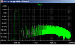
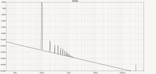
The two plots you gave with 100Hz, the first with NS and about -60dB/decade harmonic roll-off is very good. Also the first low order harmonics are -120dB below fundamental, so low that they would be hard to measure let alone hear.
The second without NS has about -30dB/decade, but with the first low order harmonics at -120dB below fundamental you have a safety margin of +80dB (below 1% needed for audibility). So even if you weighted the higher harmonics they are unlikely to get to -40dB to become audible (at least at the output level used here).
You can conclude that 1) NS does in fact reduce high order distortion, and 2) that the distortion even without the NS is not likely to be audible.
---
Regarding the Blomley approach, which uses 1) current drive of the splitters, and 2) non-switching in the power stage. The use of current drive of the splitters increases the amount of high order distortion compared to ordinary voltage drive splitting. Current drive of the splitters causes a faster transition through the zero-cross and a doubling of the rate when weighted with say +40dB/decade (double differentiator) gives 4 times the level of higher harmonics, that's a net increase of +20dB/decade. So unless current drive of the splitters can reduce the level of higher harmonics by -20dB/decade at the same time then you are not getting ahead by using current drive of the splitters.
An exception might be in the extreme case where the switching rate at the zero crossing is so fast that the majority of the higher harmonics are pushed above 20kHz where they don't affect the audible range (assuming there's not much other nonlinearites to created demodulation into the audio band by intermodulation). Antoinel's Class-aP (Post 5) would seem to fit into this category if the switching rate is fast enough. I'd be interested to see FFT plots and some D2 values for any of Antoinel's Class-aP amps.
Cheers
... for the comprehensive scope and extensive scale of your tremendously diligent and very kind response. For which, myself, and I reasonably anticipate many others are extremely grateful.
I respectfully offer to you the same apology and explanation for delay as with Hugh above.
The clarity and thouroughness of your answers have both informed and inspired my efforts in seeking to overcome the issues he has indicated.
Their substance has provided me with the confidence to approach these problems from different directions and explore some 'outside the box' possibilities knowing now that there is a well bounded function space within which to place any potential solutions.
Thank you once again,
Cheers, ian
I experimented with a version of Blomley's design in the '70s. Using very ordinary slow transistors, I saw crossover distortion. Not surprising, really, as several parts of the circuitry need to be very agile. Now, with modern devices, there's every opportunity to revisit the concept and end up with an excellent amplifier. Major advantages are freedom from the usual problems associated with class AB designs and relative simplicity.
I subsequently happened to bump into Peter several years later, and he said he'd moved onto a much better solution! Didn't say what it was though...
I subsequently happened to bump into Peter several years later, and he said he'd moved onto a much better solution! Didn't say what it was though...
So, from the above and after a great deal of effort to confirm the following:
Although I would dearly wish to be proved wrong about this. My findings to date are that the non-switching amplifier topologies which are presently well understood will in all likelyhood consistently deliver this unsatisfactory odd even harmonic profile imbalance.
This, it would appear, is generally because they are, as with any conventional AB or fully balanced amplifier, in essence, made up of two 'separate' near identical output units. Which I suggest with a suitably requisite measure of NFB will, of necessity, act together to cancel and thereby reduce the even harmonic series.
I am continuing to work, so far with some notable successes, on developing a class of non switching output stage that offers every benefit of these but without any of their all too apparent disadvantages. Which, in your post, you have been kind enough to detail.
Please consider this my personal note of thanks to you for providing the impetus to look deeper into addressing and identifying those means and methods necessary to overcome these last remaining issues.
One example of which I include below for comments.
Thank you Ian, a great post.
I cannot offer substantial proof for my assertions in my early post. This is because I design and manufacture amplifiers for the audiophile market and work on critical listening tests, an attempt to create a better mousetrap but without the usual corporate R&D team with expensive labs. My R&D costs are minimal and based on many thought experiments. I have tried to involve local Universities in psychoacoustic study, but of course they are interested in corporate investment. I have spend money and time I am ashamed to recount in developing many amps, starting with the original AKSA, then the Lifeforce, the Maya I, the Soraya, the NAKSA, the SAKSA and the latest the Maya II. All are quite unrelated but represent a steady improvement of sound quality over 18 years.
I moved to mosfets in 2011. Modern mosfets are so fast, so easy to drive, so electrically robust and thermally strong that I feel they cannot be ignored, particularly as they are now inexpensive.
I have worked with local engineers in the non-switching area, and one, Paul Bysouth, has been quite successful with one NS amp which sounds very good, on par with my flagship amp which is not NS in fact. But his amp is more complex, and the H5/H7/H9 artefacts appear to be about the same as my non-NS design so on balance I do not see much advantage. In light of the last poster it could be related to the speed of the correction transistors; like error correction this technology requires actives which are perhaps a speed order of magnitude higher than the outputs, which is problematic.
I have found that a linear, decreasing harmonic profile sounds very natural, but measures badly. If H2 starts at -90dB, and increasing orders drop by 10dB finishing with H5 at -120dB, the sound is very clean but cannot be criticised. OTOH, if H2 starts around -68dB, with increasing orders dropping 10dB and finishing with H5 at -98dB the sound is markedly warm, natural and rich. While we recognise a 'sound effects box' it is difficult to ignore such an amplifier, it sounds wonderful, not the same as a tube amp (with it's typical H2 starting around -45dB) but not dissimilar. All this indicates subtle, unexpected psychoacoustics, almost the negation of the zero THD yore we all look for.
My recent work is an attempt to move the switching point off the crossover point. If the passive device in an AB PP output stage can switch off a few volts well into the active, device duty cycle the death throes of the passive device will be presumably lost in the high current prevailing in the active device.
The final comment concerns feedback, which in global fb amps create corrections to corrections, out to higher orders. Something seems to happen beyond about 35dB of global fb where the front to back, 'depth of image', seems to shrink, giving only 2D stereo image. Many effects influence depth of image, but fb seems to be pivotal and I cannot figure this out. This phenomenon is very clear with tube amps - notably many do not have global feedback - and it attracted my interest some years ago. My amps deliver staggering depth of image because of a radical design in the feedback. Significantly I do not deliver low THD; it's typically 0.06%, but the profile is as elegant as your last plot, linear decreasing with H5 and beyond below -100dB. A measure of excellence seems to be the percentage of the THD which comprises H2, H3 and H4. Anything over 99% such amps sound very, very good.
HD
Last edited:
- Home
- Amplifiers
- Solid State
- The Blomley Class B amplifier