Just a quick question
iv'e just seen a amplifier by technics which says it's new-class-a
how does it differ from standard class a.
The amp does have auto bias controll maybee thats got summink to do with it
please tell us in simple tearms this is mentioed on diy audio.com but it's too complicated for my poor brain
cheers
re; Technics class A
You won't learn much from their marketing dept. You'd have to take one apart and have a look.
For example, their "Class AA" cirquit was two amps, both feeding the speaker via a resistor bridge. One was class A, the other was class B. The idea being that the class A amp stage fed the load, while the class B stage presented a high impedence load to the class a stage by supplying most of the load current. The class A stage also filled in the crossover region, for the time it took for the class B transistors to conduct. You'd think that Class AA is more class A than class A is, from the hype.
This type of cirquit was described in Electronics World magazine ( it may have been Wireless World at the time) by Dr Sandman, who later fought a Patent battle with Technics, claiming that they nicked his idea. I don't think he was successful though.
Dr Sandman's circuit is described in JLL Hood's book on power amps.
So maybe " new class A " is even more class A than class AA was
LOL
ok cheers dude thats a good explination
so have you ever heard one of theise amps
do ya think they sound good anyone..
heres a link to the amp i want
please dont beat me to getting it if you like it lol
http://cgi.ebay.co.uk/ws/eBayISAPI.dll?ViewItem&item=3091248698&category=3280
i know it's not that amazing but well i quite like the look of it
Don't know the new class A stuf but I have here an old (10 Years) Class AA amp from technics (SUVX 800) It sound is very decent, maybe even very good.
From the power rating (100w RMS@8ohm) and the consumed power (890watt) I think it's a class A type, it has dual power transformers, fairly big power capacitors and a huge heatsink inside (approx 15 cm high, 35 cm long with fins of 8 cm long) etc.
The old amp is better than my new HT amp (sony STR-DB1080QS) so I think I'm in for something new.
Re;- new class A
From the info on the link, it looks like the bias for the output stage changes with the signal level. The idea is that the bias level is low when the signal is low, and operates in class A. When the signal level increases, normally it would move into class B. Here they use a microprocessor to (predict?) that more oomph is needed, so the current is increased to cope with the demand, and the output stage remains in class A. In this way they can keep the amp cooler than one that is (dare I say it?) pure class A.
It's an interesting idea. Let me know how it sounds.
My dad owns a Technics SU-V8 and from what I recall the biasing circuity is designed so that neither output transistor turns off (as class A) although the biasing is not the same as class A.
When the output swings from positive to negative for instance the transistor does not switch off, but stays at a preset DC bias point. The same is true for the other transistor when the output swings from negative to positive.
This way neither transistor passes through the nasty <~0.7V Vbe region. The transition between following the input and staying at the bias point is non-linear, if memory serves, so as to reduce switching-like harmonics.
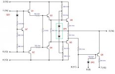
I'll try and dig out the schematics and scan something as a picture would help explain what I mean.
")
When the output swings from positive to negative for instance the transistor does not switch off, but stays at a preset DC bias point. The same is true for the other transistor when the output swings from negative to positive.
This way neither transistor passes through the nasty <~0.7V Vbe region. The transition between following the input and staying at the bias point is non-linear, if memory serves, so as to reduce switching-like harmonics.
I'll try and dig out the schematics and scan something as a picture would help explain what I mean.
Just so readers know what we're talking about, here's the SU-V7:
...and the bigger brother, the SU-V8:
Also is there any chance of a moderator moving the thread - the SU-V series (to the best of my knowledge) all have fully discrete output stages, cheers.
An externally hosted image should be here but it was not working when we last tested it.
...and the bigger brother, the SU-V8:
An externally hosted image should be here but it was not working when we last tested it.
Also is there any chance of a moderator moving the thread - the SU-V series (to the best of my knowledge) all have fully discrete output stages, cheers.
new class A
annex666 is on the right track
new class A is an innovative bias circuit that keeps the output transistors in the ready state, eliminating crossover distortion, though keeping idling current low in order for more efficiency
- some models had computer drive which had an onboard microprocessor controling Icq of the output stage based on thermal and signal parametrics.
the sound of them?...
fantastic to say the least (well the amps from '78-91) - i should know by now - i have around 75 or so Technics amplifiers in my collection now (some models including SU-V2,V3,V4,V5,V6,V7,V8,V9,V1X,V2X,V4X,V6X,V8X,V40,V50,V60,V90D,V460,SE-A3MK2,SE-A5,SE-A7,SE-M100,SU-500,600,700,800,810,SU-G50,70,90,SU-Z22,Z400,Z600,Z780(SU-V78),SU-Z980(V98),SU-Z65 - a few recievers SA-TX50,SA-R430,R377 Hi Density SU-X90 SU-X101,X102
the best bits being clean sound, lots of current, wide dynamic range & loads of good bass - their bad point is they run quite warm and some models heatsinks leave a bit to be desired
http://www.geocities.com/technicshifi/Bias.html
the SU-V series is Technics Full width Integrated Amplifier series
not all were fully discreete and in fact some of the best sounding werent... (SU-V4X) - the SVI Hybrid ICs were infact excellent (now before the solid state buffs groan `bout the ICs - a few things bout them) Being a Hybrid IC they're infact discreete components on 1 substrate - much like the STK series BUT! better than the STK, the SVI features Complimentary Symmetry & all the resistors are ALL SMD rather than the film resistors in STK
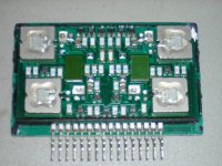
http://www.geocities.com/technicshifi/SVI2004A.JPG a typical output stage design of Technics
a look at the internals
Keep listening
any Questions? - Email
-Baily
annex666 is on the right track
new class A is an innovative bias circuit that keeps the output transistors in the ready state, eliminating crossover distortion, though keeping idling current low in order for more efficiency
- some models had computer drive which had an onboard microprocessor controling Icq of the output stage based on thermal and signal parametrics.
the sound of them?...
fantastic to say the least (well the amps from '78-91) - i should know by now - i have around 75 or so Technics amplifiers in my collection now (some models including SU-V2,V3,V4,V5,V6,V7,V8,V9,V1X,V2X,V4X,V6X,V8X,V40,V50,V60,V90D,V460,SE-A3MK2,SE-A5,SE-A7,SE-M100,SU-500,600,700,800,810,SU-G50,70,90,SU-Z22,Z400,Z600,Z780(SU-V78),SU-Z980(V98),SU-Z65 - a few recievers SA-TX50,SA-R430,R377 Hi Density SU-X90 SU-X101,X102
the best bits being clean sound, lots of current, wide dynamic range & loads of good bass - their bad point is they run quite warm and some models heatsinks leave a bit to be desired
http://www.geocities.com/technicshifi/Bias.html
the SU-V series is Technics Full width Integrated Amplifier series
not all were fully discreete and in fact some of the best sounding werent... (SU-V4X) - the SVI Hybrid ICs were infact excellent (now before the solid state buffs groan `bout the ICs - a few things bout them) Being a Hybrid IC they're infact discreete components on 1 substrate - much like the STK series BUT! better than the STK, the SVI features Complimentary Symmetry & all the resistors are ALL SMD rather than the film resistors in STK
http://www.geocities.com/technicshifi/SVI2004A.JPG a typical output stage design of Technics
a look at the internals
Keep listening
any Questions? - Email
-Baily
Attachments
I remember that I once had a Technics amp on my workbench that had some special bias circuitry. Most of the amp was discrete but the bias-control circuit was a small IC (or hybrid) the size/shape of a small DC/DC converter. As far as I remember they used signal-dependant bias.
Another principle used by Technics was a bridge circuit consisting of a full-swing class AB amp and a class A correction amp that could deliver high current but was only run at a few volts (if not even less than one volt). The load was connected across both outputs. An error voltage was derived consiting of:
errorvoltage = inputvoltage * gain - voltageacrosstheload
This error voltage was the input signal of the class A correction amp.
Regards
Charles
the sound of them?...
I remember the relief when i upgraded from one of the Technics 'New class A' wonders to a NAD in the early eighties. Not that the NAD didn't suk; it just did it in a more musical way
No.
most of these contraptions are designed in an attempt to improve on traditional ClassAB.
However, a properly designed and built ClassAB can be impeccable in both measurement and sound quality. Many will contend that the best ClassAB cannot match the best ClassA. Yet others will say one is as good as the other.
These contraptions will never better the best ClassA.
And having listened to a few, I will contend that they don't even match a mediocre ClassAB.
It should be recognized that bias circuits that prevent the "other" transistor from turning off in an otherwise class AB amplifier can improve the sound a bit by mitigating some of the switching distortion. HOWEVER, this is not class A and DOES NOT eliminate static crossover distortion.
Static crossover distortion is caused when the net transconductance of the output stage changes as the signal-handling is transferred from one device, through a sharing region, then to the other device.
In Class A, both the upper and lower devices are contributing roughly the same transconductance to the signal path through the entire signal swing. Merely preventing one transistor from turning off does NOT prevent its transconductance contribution from going very small or to zero.
Another very important point about true class A is that the rail current drawn by the power transistors is largely sinusoidal (when a sinusoid is applied), as opposed to a nasty half-wave-rectified waveform. Such nasty current waveforms running around in a class AB amplifier, if not dealt with carefully, can harm the sonics. These quasi-class-A non-switching gizmos still largely have those nasty nonlinear currents running around.
Finally, there is dynamic crossover distortion, where the output transistors are unable to change their current fast enough to follow the signal, often as a result of too low base suckout current and/or too low ft. The non-switching adaptive bias circuits that in a static sense do not permit an output transistor to turn off do not necessarily eliminate this form of crossover distortion either.
Cheers,
Bob
Mr Cordell,
Is this also your analysis of the Krill Dunlap amplifier which uses a similar biasing scheme? here: http://www.diyaudio.com/forums/showthread.php?s=&threadid=134619
Is this also your analysis of the Krill Dunlap amplifier which uses a similar biasing scheme? here: http://www.diyaudio.com/forums/showthread.php?s=&threadid=134619
Here's some detailed technical info from a (Technics / Matsushita) course I did on the CLASS AA principles back in the 80's.
This gives some quite detailed info as to how it works.
Sorry - file too large - even though it was within the permitted size...
So here are links to the three pdf's
File1
File2
File3
This gives some quite detailed info as to how it works.
Sorry - file too large - even though it was within the permitted size...
So here are links to the three pdf's
File1
File2
File3
By andrew T. - Any version of "new" classa or aa or any other is an attempt to improve on a traditional ClassAB but using the "name" or kudos of ClassA to make it appear better than all that went before it.
I also saw a "JVC super- A" , It was still AB. Just another marketing scheme. I saw the internal schema of the chip, just a
more complex frequency compensated Vbias circuit, but
the amp in general is still AB.
OS
- Status
- This old topic is closed. If you want to reopen this topic, contact a moderator using the "Report Post" button.
- Home
- Amplifiers
- Solid State
- New-Class-A ? (whats it mean)