Hi all,
I am having trouble with my naim nait 5i. Unfortunately there aren't any schematics I can find. Basically there is a fault on one channel whereby it has dc offset oscillating wildly around 10v. Hooked up a scope and there is indeed a massive waveform oscillating at different frequencies. After about 5 minutes it settles down, although I suspect it's not heat related as when I power cycle it returns instantly.
One strange thing I did notice os that when I power off the output sticks to the positive rail until the caps discharge. Could be a clue...
I have checked all resistors as best I can. But I'm stumped at where the white noise is coming from and why the output sticks when power is turned off.
Help!
What about capacitors - particularly in the negative feedback decoupling arm to earth, could there be a cold solder joint that is affected as the amplifier warms up. I have one of this model Naim it is supposed to be left powered up all the time presumably so the internal temperature is constant and humidity in the air kept at bay to avoid any corrosion or contamination of components.
Though the Nait 5i and other late model electronics follow the basic amplifier designs of the original Naim products, newer SMD versions have tightly packed layouts and will be difficult to fault find and repair properly. Unless you have the training and practice needed to avoid further damage when testing and fault tracing, you risk not having anything worth much at the end.
Really, Naim service may be expensive but at least you will be satisfied. Do this or at least get a quotation before tinkering as few people will be able to help you via a forum without you both having full schematics. Where they exist, it means strict confidentiality so its unlikely there will be many who can help with direct advice.
I wouldn't necessarily assume that 'power cycling' indicated a non heat related fault. The main heatsink is the case and that lies underneath the electronics which are then subject to the slow temperature rise and fall of the PCB and air trapped inside. With the cover removed, cooling may be faster but still lag room temp. quite a bit.
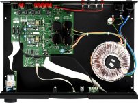
Attachments
Thanks gents. I did feed it 1khz signal which doesn't show on the output. I did however notice what seems to be capacitor ripple on the scope so I'll double check the joints as they all seem to measure fine. Any thoughts on the rail showing on power off?
These amplifiers make a noticeable pop at turn on - probably due to unequal charging rates of capacitors. The discharge rates on switch off could work in the same proportion in reverse.
In mentioning the capacitor in the feedback decoupling arm, touching the top of the case for this with a finger could give some indication of what the problem might be. The signal there is quite low but this capacitor is an input to the inverting input terminal. I expect there would be an audible result that you can compare with the channel that is working.
I have never removed the cover to look inside my Nait 5i and if it needs to be serviced I will take it to the Naim dealer who sold it to me.
Naim recommend a re-cap after 8 years if my memory is correct. I have had mine for longer than this but have no immediate plans for this, but
I would be prompted to think accordingly if it developed a fault.
I would look on that as plus point if I sell or trade for a newer model.
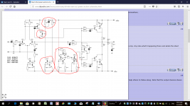
I found this which should be similar if someone can give me some advice Naim XS2 power section schematics
I found this which should be similar if someone can give me some advice Naim XS2 power section schematics
As far as I am aware the Nait 5i uses the classic layout used in previously in earlier Naits 1,2,3, and 5. I am aware that there are clone versions of 1 and 2 and the NAP140 power amplifier - the subject of an ongoing thread elsewhere on this site.
The X2 circuit has elements of the original but the Vas has been converted into a cascode amplifier and there are changes to the CCS loading - seemingly intended also to control output Iq and also for current limiting thereby obviating the classic load line limiting protection.
Attachments
Been a while since I got to have a look at this again. Some measurements. The circuit definitely looks similar to the XS2.
If I measure across D1 and D2 I get 62v across one and 10v across the other. On the other channel I get 35v which is the rail voltage. I did notice one of the outputs gets very warm. Im using a dbt naturally. Do I have a shorted output or diode? I suspect this is why I get roughly 25v dc when I have it powered as the feedback fights to bring it back in line. When I power off the output sticks to the rail.
If I measure across D1 and D2 I get 62v across one and 10v across the other. On the other channel I get 35v which is the rail voltage. I did notice one of the outputs gets very warm. Im using a dbt naturally. Do I have a shorted output or diode? I suspect this is why I get roughly 25v dc when I have it powered as the feedback fights to bring it back in line. When I power off the output sticks to the rail.
Member
Joined 2009
Paid Member
The circuit may well go to a rail on power down because it discharges the caps asymmetrically - but surely the amp has an output relay which disconnects the speaker immediately on power down so the speaker never experiences an issue. The asymmetric discharge is no big deal by itself - unless of course the 'good' channel shows different behaviour.
What frequency are the oscillations ? to be instability due to the feedback loop they'll be very high, in the radio range; if it's the output stage oscillating (the Sziklai for example) it'll be way up there in the tv range.
Warm outputs means lots of current flow. With no load the current must be flowing from rail-to-rail through the output stage. That does seem like a clue for a problem somewhere in the output stage. Could be helpful to measure voltage drop across the various resistors in the output stage to see where the currents are flowing. Best if you know the value of the resistors, but even comparing the good and bad channel will teach something useful.
Last edited:
Member
Joined 2009
Paid Member
What about capacitors - particularly in the negative feedback decoupling arm to earth, could there be a cold solder joint that is affected as the amplifier warms up. I have one of this model Naim it is supposed to be left powered up all the time presumably so the internal temperature is constant and humidity in the air kept at bay to avoid any corrosion or contamination of components.
Naim amps of old have poorly designed thermal control, they rely on closed box and stable ambient. I was a bit surprised to see how crap was the design and I re-designed this part when I built my clone of a NAP140. No idea if this applies to the NAiT 5 of course. But generally, with modern electronics there should be no need to keep them powered up. There should not be exposed copper or iron that would be susceptible to corrosion.
That 52V DC offset at the output would tell you there is a serious problem. Connecting a normal speaker to it could be doubly disastrous, as we don't expect more than a few tens of mV there. The problem is most likely with the output stage transistors - either or both TO3P style power transistors or SMD SOT223 style driver transistors. The output transistors at least, will be selected and matched types, likely marked with Naim NAXXX house codes. I'm not certain but the drivers will probably retain their industry standard markings (which can be deciphered) but still be selected and matched too.
You can check and post some test voltages here to verify what's still working. First, check Vbe of each output stage transistor - they should all be around + or - 0.65V depending on N or P type. Then measure the voltage WRT ground, at each pin - base, collector and emitter of the drivers and output transistors. All these semis will have the same standard connections for the package type. Use a fine, sharp probe tip and a magnifier, as you don't need more shorted parts.
If the output stage otherwise measures OK, we should look at the VAS stage, particularly the transistor corresponding to the FTZ953 in the XS2 schematic. If not the same, it's probably another SOT223 type too, as these dissipate a little power - same procedure, take care.
Last edited:
The brief sticking is only on the bad channel when its turned off. Powered on it is roughly 26v with lots of movement. Ive diode tested all diodes and semis and no shorts found. Measured all resistors and they all read fine and comparable to the good channel as a reference.
Ill do some vbe measurements and see what I get. With a lot of smd components here I want to (learn) what's in front of me and why I see the readings I get before I start removing components, if that makes sense. Im far from proficient but willing to learn rather than just fix. Thanks for the guidance.
If you need help, I think it wise to at least post some more voltages around the output stage, so it can be seen to be OK or suspect. Then I would do the same for the voltages of the FZT853/953 (or similar) types used in the voltage amplifier stage. Otherwise, we don't have much that's solid, to go on.
I have worked on quite a few earlier Naim amps and whilst the bigger models are tough enough to survive abuse, the early, low power Naits were easily fried. This i5 isn't really a Nait but a virtual NAP design of about NAP110/140 capability. I guess it will have a new set of vulnerabilities in SMT and the updated current limiting design mentioned by mjona has likely added some new ones.
I find it just about essential to note all node voltages and simulate what should be occurring with an easy sim. program like Ti Tina (free at Texas Instruments website). This helps me at least, to become familiar with newer or unusual design amplifiers. This is probably the situation for a lot of folk here, where there is also a mix of new and old topologies , like the now rare quasi-complementary output stage. .
I mentioned the feedback decoupling arm capacitor C602 in the X2 circuit as a possible cause needing to be eliminated. If this is a special polymer capacitor with a mix of liquid and solid polymer I would be extremely suspicious - since this type of capacitor has more leakage than other types.
If there has been deterioration over time with either electrolyte the capacitor could be holding by a very thin thread - slow charging on power up and rapid release at switch off. I suspect this would pass the usual meter on resistance range test unless a 1k resistor was included in the measurement.
It would be interesting to see what happens to the base voltage of Q602 at switch off.
There is more info on polymer caps Polymer capacitor - Wikipedia
- Status
- This old topic is closed. If you want to reopen this topic, contact a moderator using the "Report Post" button.
- Home
- Amplifiers
- Solid State
- Naim Nait 5i