Hi!
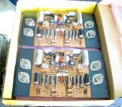
Here is my PCB-artwork from my Leachamp (with transistors on the PCB) contained in 6 pdf-files:
SchematicTop-layer
Bottom-layer
Names of devices
Values of devices
Mounting

Good luck
wopo
Here is my PCB-artwork from my Leachamp (with transistors on the PCB) contained in 6 pdf-files:
SchematicTop-layer
Bottom-layer
Names of devices
Values of devices
Mounting
Good luck
wopo

m0tion said:Have you built the amp using these PCB designs? Any pictures or perhaps a tutorial/explaination?
if you are asking me, no, but i have built lots of the 'double-barreled' leach back in the mid 80's up to early 90's and i found the sound very good, in fact i find the sound better than japanese amps at the time....this amp drive many types of speakers with ease, we used this amps for mobile disco's...


A message that you sent could not be delivered to one or more of its
recipients. This is a permanent error. The following address(es) failed:
tonyjtec@yahoo.com
SMTP error from remote mailer after end of data:
host mx2.mail.yahoo.com [67.28.114.32]: 554 delivery error:
dd Sorry your message to tonyjtec@yahoo.com cannot be delivered. This account has been disabled or discontinued [#102]. - mta120.mail.dcn.yahoo.com
ooopss, sorry, got my e-mails mixed up, it should be tonyjtec@hotmail.com or tonytecson@yahoo.com.....
Q8 and Q9 in Leachamp do not have any function. Current in VAS is already limited by the maximum voltage that can occur on VAS transistor bases. This voltage is equal R11 or R12 multiplied by maximum tail current. In this case maximum VAS base voltage is 1.2k * 40V/12k = 4V. Vas current is limited to 3.3V/390ohm = 8.5 mA which is well below current nedded for Q8 an Q9 conduction (20mA).
This kind of current protection is effective if current mirror is used in input stage, and therefore maximum VAS transistor base voltage can't be determined.
regards, Dule
This kind of current protection is effective if current mirror is used in input stage, and therefore maximum VAS transistor base voltage can't be determined.
regards, Dule
You noticed that too, hun? I wrote Dr. Leach about this 3 years ago, and he replied back explaining how the current limit function worked, but missed the point. He must get tons of email, so I was glad to hear back, but he never took it seriously. I suspect this circuit has been there for decades and he changed something else to make it redundant, not realizing it.dulel said:Q8 and Q9 in Leachamp do not have any function. Current in VAS is already limited by the maximum voltage that can occur on VAS transistor bases. This voltage is equal R11 or R12 multiplied by maximum tail current. In this case maximum VAS base voltage is 1.2k * 40V/12k = 4V. Vas current is limited to 3.3V/390ohm = 8.5 mA which is well below current nedded for Q8 an Q9 conduction (20mA).
This kind of current protection is effective if current mirror is used in input stage, and therefore maximum VAS transistor base voltage can't be determined.
regards, Dule
You can leave out these VAS current limiters if you like. If the main output protection kicks in, the VAS current does get diverted to the output, so a limit is advisable, but like you I can't see what good this does because of the values selected.
- Status
- This old topic is closed. If you want to reopen this topic, contact a moderator using the "Report Post" button.
- Home
- Amplifiers
- Solid State
- Leach Amps PCB Artwork