That was interesting. 8ohm impedance cable (8 paralled 50 ohm coax) was shown to have no distortion between input and output.
Some sores are so old there is no scab to pick off. For a square wave input there is good reason for this. As for "distortion" this guy considers any difference distortion even if it comes from adding two signals with a frequency dependent phase difference.
More likely that coax avoids mechanical effects. A parallel wire cable with a large bass signal and a high frequency signal might have the low frequency current change the conductor spacing due to its motor effect and in turn this can modify the inductance affecting the high frequency signal. This is intermodulation distortion.That was interesting. 8ohm impedance cable (8 paralled 50 ohm coax) was shown to have no distortion between input and output.
YouTube
Thanks for the link acg.
Coax will be fairly immune to this, due to the symmetrical construction.
No 50R coax is anything like Z=50 in the audio band, series resistance dominates the inductance.
More likely that coax avoids mechanical effects. A parallel wire cable with a large bass signal and a high frequency signal might have the low frequency current change the conductor spacing due to its motor effect and in turn this can modify the inductance affecting the high frequency signal. This is intermodulation distortion.
jn has computed this too, it's so far down it's ridiculous. This thread has gotten very funny.
Yes.jn has computed this too, it's so far down it's ridiculous. This thread has gotten very funny.
Oh, no. A speaker, like a car, *has* to be run-in.Burn in de speakers ..... well, let's say it can be discussed.
And you can measure the change at the resonance frequency after 24 hours of "break-in". Suspensions become more flexible.
Last edited:
Some sores are so old there is no scab to pick off. For a square wave input there is good reason for this. As for "distortion" this guy considers any difference distortion even if it comes from adding two signals with a frequency dependent phase difference.
I have no opinion on this.
Did you watch the other 3 shorter followup videos where he plays a music signal?
Yes, we must be misunderstanding each other.scott wurcer said:We keep talking about two different things. Let me ask you a question, do you disagree that the RF characteristic impedance defines the bulk L and C (you need the speed of propagation also)? I used RG58 as an example for a reason, 8 parallel is ~250pF/ft the Polk (from a web source) is 280pF/ft so what's the problem?
My point is that an '8 ohm' cable is not 8 ohms at audio frequencies, because the sqrt(L/C) formula does not apply at audio frequencies. Such a cable (which may well be 8 ohms at RF) has L and C derived from that formula, which is what you apparently thought I was denying. I thought you were claiming that an audio cable can be 8 ohms at audio frequencies - which surprised me because I assumed you knew better.
The point I was trying to make is that a speaker-end Zobel must match the RF characteristic impedance of the cable. It does not need to match the speaker impedance (which is likely to be different) and it cannot match the audio characteristic impedance because that is not resistive and it varies with frequency; you would need something better than a Zobel network to do that and it is anyway unnecessary.
Have I clarified things or made things worse?
You Tube FAKES.
From an engineer though, not a layman...
...come on where has he gone wrong? What is wrong with the setup or the protocol? Or are you just going to yell FAKE and not dispute leave it there?
It is something that I would like to try and replicate myself if I ever find the time, but my scope may not have the bandwidth.
You have to question whether his conclusions are correct.
He clearly isn't measuring harmonic distortion.
Would a small amount of phase shift cause the difference that's being seen here? What would be the result if you measured at the driver with a passive filter installed?
He clearly isn't measuring harmonic distortion.
Would a small amount of phase shift cause the difference that's being seen here? What would be the result if you measured at the driver with a passive filter installed?
I thought you were claiming that an audio cable can be 8 ohms at audio frequencies - which surprised me because I assumed you knew better.
Have I clarified things or made things worse?
No I never claimed that in fact I specifically said the actual impedance at audio frequencies did not matter at all, the line is too short. I did say the RF impedance and speed of propagation are all you need to get a very close number for the bulk L and C for a very short line.
Unfortunately Smith charts don't have much resolution at tiny fractions of a wavelength.
I have no opinion on this.
Did you watch the other 3 shorter followup videos where he plays a music signal?
Yes, there is nothing magic here. Make two cables where one has 10 times the capacitance and one tenth the inductance, I would expect the overshoot and phase properties to be different with the same load. Simply think of the damping factor of an RLC circuit it contains the same sqrt(L/C) as the RF impedance, not really a coincidence but RF vs audio does not figure into it.
Last edited:
Most Smith charts assume a resistive frequency-independent characteristic impedance too.scott wurcer said:Unfortunately Smith charts don't have much resolution at tiny fractions of a wavelength.
I haven't actually bothered to look at the Youtube demo others are talking about, but from what people say I assume someone has sent some high frequency signals down a transmission line and shown that when it is roughly matched the signal arrives relatively undistorted. In order to confuse himself and some others, he disguised the HF signals by making them from the harmonics of a square wave whose fundamental is in the audio frequency range. Hence the fundamental and maybe a few lower harmonics arrive OK because the line is short, and the higher harmonics (out of the audio range) arrive OK because at those frequencies the line is matched. Is that a fair summary?
Yes.
Oh, no. A speaker, like a car, *has* to be run-in.
And you can measure the change at the resonance frequency after 24 hours of "break-in". Suspensions become more flexible.
As I said before, it is debatable ... but I do not want to distort here, it is a topic that is also very remanded and without definitive conclusions, just like the speaker cables. Maybe you are interested in reading this link.
There are conflicting opinions from the speaker manufacturers themselves.
This link has its years, but it is totally valid. You can translate it with Google, although the part I mention is in English.
Matrix-Hifi
Click in El rincon, then 09/02/2006 Rodaje de altavoces
PS: By the way, the machining of modern engines are so precise today that they no longer need to be softening ...
")
Last edited:
Most Smith charts assume a resistive frequency-independent characteristic impedance too.
Is that a fair summary?
More importantly there is no loss (R).
I think everyone is over thinking this. Simply consider a lumped model of the line R, L, and C (R can probably be ignored) against a load resistor. It can be under damped and it can have peaking but the damping factor is related to the same sqrt(L/C) as the RF impedance. Q, damping factor, Z, etc. contain these same relationships and you use them to design L/C filters all the time.
So the same 8 ohms works out no matter how you look at it, I think that's the beauty of it.
Microphone measurements
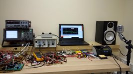
OK, let's see what we've got here.
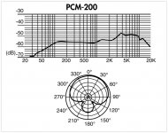
I didn't find my Behringer condenser microphone, so I used a dynamic one - not as neutral (designed particularly for voice), but anyway ok for comparative analysis.
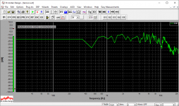
The overall frequency response (measured with MLS signal) of the whole system - amplifier, cable, speaker, microphone, mic-preamp - is horizontal enough up to some 8KHz. Certain "presence peak" is clearly visible - it's coming from the microphone. What I didn't expect is the "hollow" at 500Hz - we didn't see any impedance or distortion anomaly there when measured at the speaker terminals earlier. I believe it's related to some acoustic effect (reflection in the room?).
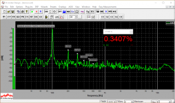
All the spectrums show clear H2 and H3 dominance - neither the speaker nor the microphone produces any high-order stuff - example at 100Hz with 15m cable is attached.
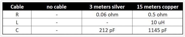
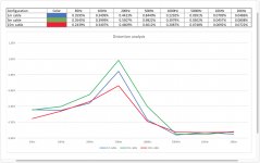
So - the resulting curves. The highest distortion is shown with the 3m cable. Then goes the 1m one - ok, that's what I expected. But then the 15m cable goes even lower. The one, having the highest Z, performs the best. My thinking - it "normalizes" the speaker impedance, as a far-end Zobel would do.
Next step would be trying some Zobel network at the far end of the shorter cables - Nelson Pass suggested this approach at the beginning of this thread - now it's a good time to test the thing.
Any thoughts are welcome
Cheers,
Valery
P.S. I continue trying to find by Behringer - it's much more neutral in terms of the frequency response, giving less distortion at the same time.
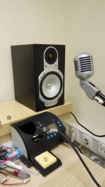
P.P.S. Just noticed on the picture - I've mounted the microphone with its back "looking" at the speaker... not catastrophic, but not good - to be corrected next week
OK, let's see what we've got here.
I didn't find my Behringer condenser microphone, so I used a dynamic one - not as neutral (designed particularly for voice), but anyway ok for comparative analysis.
The overall frequency response (measured with MLS signal) of the whole system - amplifier, cable, speaker, microphone, mic-preamp - is horizontal enough up to some 8KHz. Certain "presence peak" is clearly visible - it's coming from the microphone. What I didn't expect is the "hollow" at 500Hz - we didn't see any impedance or distortion anomaly there when measured at the speaker terminals earlier. I believe it's related to some acoustic effect (reflection in the room?).
All the spectrums show clear H2 and H3 dominance - neither the speaker nor the microphone produces any high-order stuff - example at 100Hz with 15m cable is attached.
So - the resulting curves. The highest distortion is shown with the 3m cable. Then goes the 1m one - ok, that's what I expected. But then the 15m cable goes even lower. The one, having the highest Z, performs the best. My thinking - it "normalizes" the speaker impedance, as a far-end Zobel would do.
Next step would be trying some Zobel network at the far end of the shorter cables - Nelson Pass suggested this approach at the beginning of this thread - now it's a good time to test the thing.
Any thoughts are welcome
Cheers,
Valery
P.S. I continue trying to find by Behringer - it's much more neutral in terms of the frequency response, giving less distortion at the same time.
P.P.S. Just noticed on the picture - I've mounted the microphone with its back "looking" at the speaker... not catastrophic, but not good - to be corrected next week
Attachments
-
 IMG_20180420_210114.jpg94 KB · Views: 191
 -
 IMG_20180420_210029.jpg78.1 KB · Views: 181
 -
 PCM_userguide 2018-04-20 23-14-04.jpg144.6 KB · Views: 308
 -
 Cable_analysis_table-01.PNG 2018-04-20 23-20-29.jpg105.3 KB · Views: 179
 -
 10 Frequency response.PNG49.7 KB · Views: 184
 -
 03 00100.PNG58.2 KB · Views: 71
 -
 Analysis (1 page) 2018-04-20 23-17-26.jpg272.4 KB · Views: 78
Last edited:
You could actually use as large a cable as you want, just solder and inch or two (3 cm) of 14 gauge to each end to go into the quick connect terminals (preferably solid copper, as in Romex style house wiring). This won't add significant resistance to a cable that's several feet (or meters) long.In my case, this shows, 2.5 mm2 speaker cables is overkill. I was not expecting any sound difference anyway, that was just for fun.
2.5 mm2 is the right choice ....Because it is the maximum accepted by Quick connect terminals.
( gauge #14 is 2.1 mm2 )
You're confusing impedance with characteristic impedance.And a 75 ohm shielded coaxial cable also has that characteristic impedance according to its high working frequencies, as well as a two-conductor TV cable in unshielded parallel had a characteristic impedance of 300 ohms.
As already said, neither a speaker has 8 ohms in DC (it is always lower) this characteristic impedance normally corresponds to a test signal of 1000 Hz with which the manufacturers measure their speakers. It is not standardized, it is generalized, which is not the same thing. In a twoofer and a tweeter the 8 ohms of characteristic impedance are measured at other frequencies, if I remember correctly, they were generally measured at 600 Hz and 10000 Hz,
respectively
So I do not see how these generic devices can be used for boxes of 4, 6, 8 ohms indistinctly.
Impedance of speakers and speaker drivers (and resistors, capacitors and inductors) is measured at various frequencies, as you indicate.
Characteristic impedance is a very specific term that only applies to a transmission line, which is also a very specific term. None of this applies at audio frequencies unless you have a cable that is miles long.
Characteristic impedance - Wikipedia
Transmission line - Wikipedia
The transmission line article spells things out, though I don't know where that exact 30kHz figure comes from:
"Ordinary electrical cables suffice to carry low frequency alternating current (AC), such as mains power, which reverses direction 100 to 120 times per second, and audio signals. However, they cannot be used to carry currents in the radio frequency range,[1] above about 30 kHz, because the energy tends to radiate off the cable as radio waves, causing power losses.
...
Transmission lines become necessary when the transmitted frequency's wavelength is sufficiently short that the length of the cable becomes a significant part of a wavelength."
Even at half the speed of light (electromagnetic signals go slower in wire and cables than in a vacuum), the wavelength of a 20kHz sine wave is several miles. If your speaker cable is a significant part of that length, you might have other problems.
Here's an interesting article on characteristic impedance. One interesting property of a transmission line is the characteristic impedance is constant, and does not change with frequency.
Characteristic Impedance | Transmission Lines | Electronics Textbook
Last edited:
You're confusing impedance with characteristic impedance.
Impedance of speakers and speaker drivers (and resistors, capacitors and inductors) is measured at various frequencies, as you indicate.
Characteristic impedance is a very specific term that only applies to a transmission line, which is also a very specific term. None of this applies at audio frequencies unless you have a cable that is miles long.
Characteristic impedance - Wikipedia
Transmission line - Wikipedia
The transmission line article spells things out, though I don't know where that exact 30kHz figure comes from:
"Ordinary electrical cables suffice to carry low frequency alternating current (AC), such as mains power, which reverses direction 100 to 120 times per second, and audio signals. However, they cannot be used to carry currents in the radio frequency range,[1] above about 30 kHz, because the energy tends to radiate off the cable as radio waves, causing power losses.
...
Transmission lines become necessary when the transmitted frequency's wavelength is sufficiently short that the length of the cable becomes a significant part of a wavelength."
Even at half the speed of light (electromagnetic signals go slower in wire and cables than in a vacuum), the wavelength of a 20kHz sine wave is several miles. If your speaker cable is a significant part of that length, you might have other problems.
Here's an interesting article on characteristic impedance. One interesting property of a transmission line is the characteristic impedance is constant, and does not change with frequency.
Characteristic Impedance | Transmission Lines | Electronics Textbook
It is exactly what I have tried to say, but you have not understood me or taken the necessary time to analyze my post.
Characteristic you should determine it as typical depending on the frequency of work.
It is a value determined by how L, C and R act when they carry an alternating current signal of a certain value.
I'm not confusing anything and I do not need to read wikipedia, are you an amateur or an electronic technician like me?
Do you dare to calculate a problem that I pose to you?
Based on a certain voltage drop in a resistance, and the current that passes through it (both measurable), it calculates the value of the same. Give me a practical effect with the scheme and the values.
- Status
- This old topic is closed. If you want to reopen this topic, contact a moderator using the "Report Post" button.
- Home
- Amplifiers
- Solid State
- Speaker cables don't influence harmonic distortion!