Hi All,
I have a broken Niles SI-250 from the mid 90's, by looking at it, it seems like the PSU is the problem since it has signs of overheating all over the place, specially the resistors, I wonder if I should try fixing it or just re-purpose it for something else, does anybody have any experience with these?
I called the Niles support and they said they do not have any schematics nor service manuals for it, so I guess they are disposable.
I have 3, LM4702C amplifier modules (xd218.com) coming my way so I'm wondering if I should use the SI-250's huge transformer and other components and create something with it or if I should give it a try?
Any suggestions?
Thanks,
Alex
Attachments
What are the sympthoms, does it play music at all, DC on the outputs or just over-heat?
Do you have correct voltages coming out of the PSU board? If so, then it's something else. Generally I would look elsewhere, PSU are typically not the failure point, unless there was a catastrophic short.
There is some heat coloration showing - but it is almost 25 years old. They seem to have added heatsinks and higher wattage parts as required.
It could be a low-voltage part on the PSU though - say a 12V or 15V for a pre-amp or relay/protection circuit.
Thanks for your answer @bullittstang, it doesn't have any output at all, all the lights come on, even the relay manages the turn on mode works and everything, there's no DC offset either.
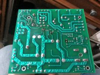
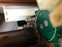
I did clean up the PCB before taking those pictures but there were signs of water damage and rust in some resistors, I really believe there was a catastrophic short since the little 3 pin connector in the middle is completely toasted, even the thin wires attached to it, see pictures, there are some signs of water under the resistor.
I never tested the Voltage coming out of the PSU but I don't think its even making it into the reserve caps because I checked them and there was no voltage on them at all, thus I don't believe DC is making it into the Amp.
Attachments
Hopefully you have a Dim Bub Tester, if so I would run the DBT in series with your wall power (120V) start with a 25w or 40w bulb.
Then without anything connected except the 120V test the output connectors on the PSU board and see if you are getting voltages and what they are. Share that with us.
I agree it could be a bad failure, but the PSU could still be good, you just need a new connector on that wire.
The PSU and transformer are 60% of the cost of a amp so I wouldn’t cast it off until you determine if it is actually working .
Sounds like you have verified the toroidal is putting out A/C? Is that correct?
The board that little connector drives may have something shorted on it. the problem may not be on the power board. Those connectors are only good for about an amp.
The fuse may be blown. Check the fuse reads 0 ohms unplugged.
Common problem is the electrolytic caps, the big things labeled 18000 uf, short out. If the water was white, that indicates one of those leaked. They are expensive though, $25 or more. I wouldn't start by just shotgun replacing those unless you intend to follow through and fix all the cheaper parts of the amp. Check if one of the mains caps (18000) reads short on the DVM ohms scale (power unplugged). All big electrolytic caps read low for a while, but they should build up to 9999 eventually. First check at 0 vdc to avoid blowing the meter fuse.
Last edited:
Hopefully you have a Dim Bub Tester, if so I would run the DBT in series with your wall power (120V) start with a 25w or 40w bulb.
Then without anything connected except the 120V test the output connectors on the PSU board and see if you are getting voltages and what they are. Share that with us.
I agree it could be a bad failure, but the PSU could still be good, you just need a new connector on that wire.
The PSU and transformer are 60% of the cost of a amp so I wouldn’t cast it off until you determine if it is actually working .
Sounds like you have verified the toroidal is putting out A/C? Is that correct?
Thanks again bullittstang, I don't have a DBT but I will make one, it's always a good idea try things with it first.
Unfortunately it's not clear to me what are the outputs that's why I wanted to find an schematic but I will follow the lines and try to figure that out.
Yes, I have tested the Toroidal and both secondaries have 45 VAC, I guess that's good, isn't it?
The board that little connector drives may have something shorted on it. the problem may not be on the power board. Those connectors are only good for about an amp.
The fuse may be blown. Check the fuse reads 0 ohms unplugged.
Common problem is the electrolytic caps, the big things labeled 18000 uf, short out. If the water was white, that indicates one of those leaked. They are expensive though, $25 or more. I wouldn't start by just shotgun replacing those unless you intend to follow through and fix all the cheaper parts of the amp. Check if one of the mains caps (18000) reads short on the DVM ohms scale (power unplugged). All big electrolytic caps read low for a while, but they should build up to 9999 eventually. First check at 0 vdc to avoid blowing the meter fuse.
Hello Indianajo,
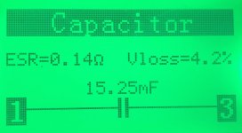
Thanks for chiming in, the fuse is good and the caps read OK, not perfect but they don't seem to be shorted, I guess they still need to be replaced but I want to find the mayor problem first. I tested the resistance and they both started building up until I disconnected them around 3.3 K ohms since that's where the count started to really slow down.
I didn't see any white liquid or marks besides from some calcification that you can see under the resistors from the pictures I posted before.
I'm attaching the Caps read.
Thoughts?
Attachments

no it is not, it is what happened with Chinese glue after 20 years. The amp has an opamp on the input, correct? There is a separate tiny board with volume controls, can you get the signal from it. The amp itself follows the topology of the fine Japanese amplifiers and the sound was good.sign of water damage and rust in some resistors
There is a separate tiny board with volume controls, can you get the signal from it.
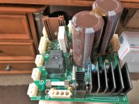
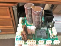
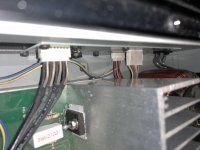
Thanks for chiming in dimitri, there's a long board in the front of the amp with the volume controls you mention and it also has all the LEDs, there are 4 cable pairs that come and connect another smaller but more papulated board in the back of the amp which has the Input RCAs, Cascade Output RCAs, Speaker Outputs and a switch for bridged use, please see attached pictures.
Not sure what are you suggesting to test there tough, please apologize my ignorance but can you please clarify?
PS. I'm not an expert by any means, I'm just a DIYer getting into amplifiers and trying to repair this, a Carver TFM-15 and others that I got for practice purposes
 , so I really appreciate your will to help me and your patience.
Attachments
Today I finally got some time to work on this amp, basically I decided to give it a chance and re-solder every single component in the PSU circuit and replaced the little 3 pin wire housing that was toasted.
After testing the output terminals to make sure there wasn’t DC offset I connected the speakers and viola, there’s music coming out, then I turned up the volume on the preamp and I could hear a little clicking and the sound vanished, then just for testing I turned the volume down and powered the Amp off and back on and the music sounded again, and so on.
Since this amp can work on bridged mode I gave it a try and that works just fine, I can turn the volume up as much as the speakers can handle and no problems at all.
Any ideas what should I be tackling next?
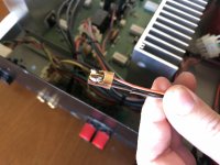
Attached are the pictures of the relay that goes off when I turn the gain up.
Thanks,
Alex


After testing the output terminals to make sure there wasn’t DC offset I connected the speakers and viola, there’s music coming out, then I turned up the volume on the preamp and I could hear a little clicking and the sound vanished, then just for testing I turned the volume down and powered the Amp off and back on and the music sounded again, and so on.
Since this amp can work on bridged mode I gave it a try and that works just fine, I can turn the volume up as much as the speakers can handle and no problems at all.
Any ideas what should I be tackling next?
Attached are the pictures of the relay that goes off when I turn the gain up.
Thanks,
Alex
I disassembled the input circuit today and realized that there are 2 little resistors that show signs of discoloration, so lacking of an schematic I’m trying to figure out their values from color code but I’m not sure if they are 1 or 10 kohm, what would you say from the picture?
Thanks
Thanks
Brown black black red, likely 10 k 1% resistors. It is hard to get a 100 k resistor to burn unless in tube circuits where they are dropping down hundreds of volts. I'd measure before changing, though.
Oh gee, LF353 op amp. This is primitive. Likely these are quite noisy if gain if over 10. Gain is Rf/Ri. Rf goes between pin 1 and 2. If you're any good with an iron put sockets in so you can change to something modern. Use phosphor bronze sockets so the pins don't corrode in 10 years. Likely some modern op amp will require closer .1 uf ceramic bypass caps on the power, and 33 pf around the feedback resistor, to no oscillate. Since these are jfet input you may have to go to some AD or Burr brown part to get something quiet.
Oh gee, LF353 op amp. This is primitive. Likely these are quite noisy if gain if over 10. Gain is Rf/Ri. Rf goes between pin 1 and 2. If you're any good with an iron put sockets in so you can change to something modern. Use phosphor bronze sockets so the pins don't corrode in 10 years. Likely some modern op amp will require closer .1 uf ceramic bypass caps on the power, and 33 pf around the feedback resistor, to no oscillate. Since these are jfet input you may have to go to some AD or Burr brown part to get something quiet.
Last edited:
Thanks Indianajo, you are right I tested the resistors off circuit and they both are within 1% of 10K. Good recommendation on the op amps I'll definitely look for options, so far a more "modern" direct replacement could be TI RC4558P and apparently something better would be AD AD708JNZ, thoughts?
I'd like to fix the biggest problem first, any ideas why its having the behavior I describe in post #10?
I'd like to fix the biggest problem first, any ideas why its having the behavior I describe in post #10?
I've found NJM4558 to be quite hissy at 50x gain in a mag phono circuit. At gains of 1-10 they are not objectionable. If the gain is that low the LF343 may be adequate. AD708 seems to be slightly better, in the input noise voltage spec, but I haven't used them. You need to use a fet input op amp probably, unless you really evaluate the circuit and determine that is not necessary.
As far as your protection relay taking out the sound, I would say measure the DC on the input of the relay when it is out. More than 200 mvdc, I'd say the amp stages are still faulting. Less than 200 mvdc I would say the protection detector itself has a fault. Peavey uses a diac that breaks down at more than 7 vdc in both directions. This can short in a major output transistor breakdown event. Maybe some previous tech repaired the OT's and not the protection circuit detect.
If the protection relay has no change to the coil voltage when it protects, then the contacts inside the relay can be oxidized or pitted. These often need replaced at the 10year or more boundary. One reason I believe protection relays are obsolete in this day of nfet speaker disconnect circuits.
Look around to see if there is also a thermal input (on the heat sink) to the protection circuit, that maybe has experienced a disconnect due to oxide on the connector. Connectors can be scraped off by removing and replacing. If the sensor is a snap action switch, the oxide can be inside the switch itself.
Last edited:
OK, so I tested the DC Voltage in the relay today and this is what I found:
On Stereo mode at very low volume it works and the DC voltage is as follows
Pin 1.- from -4 to 0 mv
Pin 2.- from -2 to 0 mv
Pin 3.- from -4 to 0 mv
Pin 4.- from -2 to 0 mv
Pin 5.- ~28 volts
Pin 6.- ~62 volts
When I turn the volume up the relay goes out and Pin 5 changes to ~62 volts and everything else stays the same.
On Bridged mode, everything stays as when in low volume and no matter how high I turn the volume nothing changes.
I have no idea what that means...
An externally hosted image should be here but it was not working when we last tested it.
On Stereo mode at very low volume it works and the DC voltage is as follows
Pin 1.- from -4 to 0 mv
Pin 2.- from -2 to 0 mv
Pin 3.- from -4 to 0 mv
Pin 4.- from -2 to 0 mv
Pin 5.- ~28 volts
Pin 6.- ~62 volts
When I turn the volume up the relay goes out and Pin 5 changes to ~62 volts and everything else stays the same.
On Bridged mode, everything stays as when in low volume and no matter how high I turn the volume nothing changes.
I have no idea what that means...
Last edited:
okay, 5 to 6 is the coil. That little box is one cheap sign of the coil of a relay. 28 to 62 means it is picked up. When the amp goes silent, the 5 goes to the same as 6 and the relay drops out. So something is taking the relay into protection mode (silent)
There should be a connection from 1,2,3,or 4 to the junction of the emitter resistors of the output transistors, which is the speaker output of an amp without protection. Maybe 1 & 3 is one channel and 2-4 is the other channel. Anyway, either 1,2,3, or 4 is going > the the dc protection voltage when the relay drops out, or something else is wrong with the protection circuit.
There should be a connection from 1,2,3,or 4 to the junction of the emitter resistors of the output transistors, which is the speaker output of an amp without protection. Maybe 1 & 3 is one channel and 2-4 is the other channel. Anyway, either 1,2,3, or 4 is going > the the dc protection voltage when the relay drops out, or something else is wrong with the protection circuit.
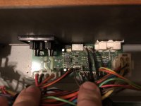
1 and 2 go straight to a harness that then goes to the input/output board.
3 and 4 go to L1-R4 and L2-R41, see pictures attached.
One thing is that when I was testing the voltage on 1-4 I forgot to change the voltage scale on the DMM and I put the lead on 5 and the relay clicked and there was the sound again, I guess the DMM acted as a jumper?


3 and 4 go to L1-R4 and L2-R41, see pictures attached.
One thing is that when I was testing the voltage on 1-4 I forgot to change the voltage scale on the DMM and I put the lead on 5 and the relay clicked and there was the sound again, I guess the DMM acted as a jumper?
The terminals at the top of the relay probably go to the speakers.
The terminals at the bottom of the relay are the coil.
The terminals in the middle are the inputs from the various emitter resistors, the white ones on the side. Those points should be roughly less than 200 mvdc from speaker ground at all times.
The components below the relay appear to be the protection circuit. D8 D9 are probably zener diodes that determine how much dc to protect against. U2 is probably some sort of protection IC - see if you can get a number off it and get a datasheet from datasheetcatalog.com
If either of those electrolytic caps leak, the protection mode may go off falsely even though the DC on the inputs to the relays are okay. Manufacturers install *****y short life electrolytic caps to make sure their product doesn't last too long less you won't buy another. Local parts stores carry only **** grade caps because repairmen want their customers to have another failure next year so they will come back. Also *****y parts houses like Allied or mcm.
Voltage jumping around when you touch meter probe to something either means you didn't hit is securely, or that is a bad solder joint. I've found bad solder joints that way, the symptom occured every time I touched a certain point with the probe. Make sure meter negative is alligator clipped securely to speaker ground when trying to find things that way. Never use two hands when probing with a meter, current across your heart above 24 vdc can stop it.
I'm usually out of it this time of night, but this is the part of the spring when I sneeze every two minutes. Trees are having sex in the air.
Last edited:
8 pins SIP. I guess the protection IC is a TA7317. Pins 2, 3 are the DC sense inputs. Pin 6 is the relay drive output. Pin 8 is the muting pin, which if it doesn't get to a certain voltage will silence the output by dropping the relay. The capacitor on that pin is a known overage problem, if it leaks the amp goes silent.
- Status
- This old topic is closed. If you want to reopen this topic, contact a moderator using the "Report Post" button.
- Home
- Amplifiers
- Solid State
- Niles SI-250 Fix or Re-Purpose?