On page 30 of the data sheet below, it shows an odd response when used as a unity gain buffer. Can someone explain the response curve at 1 volt input and below ? Seems that would make it unusable.
http://www.ti.com/lit/ds/symlink/tl072.pdf
http://www.ti.com/lit/ds/symlink/tl072.pdf
...Better to use rail to rail op amps.
R2R inputs are an un-natural abomination.
They nearly always involve two input stages working in "Class B". When the one flips-out it goes to cutoff and control transfers to the other input. The two can't really be matched (different polarities) and the "cross over" point is rarely specified except as a glitch in the input offset curves.
An externally hosted image should be here but it was not working when we last tested it.
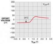
"Figure 2 As the amplifier's common-mode voltage changes from ground to the positive supply, the input stage of the CMOS amplifier completely changes from its PMOS input pair to its NMOS input pair at -2V below the 3V positive supply rail." - https://www.edn.com/electronics-blo...s--rail-to-rail--input-operation-really-mean-
The first defense is, as always Good Audio Hygiene. Don't Clip!!
When you must, don't clip unity-gain chips with wonky to-rail behavior. Run them at gain of 1.1 with a 1:0.9 input pad. (One big console ran all their unity-gain stages as diff-amps with 2:1-1:2 in-out networks.)
Attachments
Last edited:
You need to learn about RRIO opamps that use a class A single input stage and a charge pump. 15 seconds of Googling found the article attached below, which is just a rehashing of the TI OPA365 datasheet. Numerous other opamp mfrs use the same idea in several of their RRIO products
_
_
Attachments
Well I found an old NE5532 2:1 preamp with a 50 ohm series output resistor. It's doing great, no oscillations. It led me to a ground loop I hadn't noticed, silly me ran the preamp and power amp supply leads separate to their modules but did not make a ground link between grounds (DC-) of the two power supplies at the source. Did wonders for random hash noise but the tone control still breaks into an 18 usec semi-sine oscillation (55.555khz) if I turn the bass down less than ~30% or the treble up above about 70%.
Another problem this tone control has is an extreme sensitivity to coupling between the potentiometer leads (~2"). I grounded all the pot cans, wrapped the pot leads with foil. First tried grounding the foil and got more oscillation problems, removed the grounds from the foil but left it on the pot leads, now an improvement to the point that it doesn't easily oscillate unless I turn the pots as described above.
I think I'm going to try a more robust tone control circuit. I have a 10 band graphic equalizer module that sells on Ebay for $12 - 15$. It has poor definition. I tried it on my RCA Pro receiver and it just doesn't make the ringing sounds with it in. Not in, they return to crystal clear triangle type sounds (the ding type of triangle).
But no oscillation problems with it. Add in that the two band tone control does have a bit of harshness to it.
Unless you are up to a big surprise challenge, I'd skip on past the NE5532 App Note Tone Control. I did learn a lot with it, the real reason I took it on.
This circuit is too fussy, I'm about to try a new one.
Last edited:
I figure the way to make this tone control manageable is to reduce the excessive range of +- 20db. That's a ridiculous range to me, I would never use full control of bass or treble. It has pretty reasonable definition and distortion, so is worth salvaging. I usually end up scooping the midrange any way, so no complaint about the lack of mid adjustment.
Easy fix, replace the two 100k pots with a 50k and then a 25k resistor on each outer terminal. Common sense genius at work here.
I have never worked with a single opamp working two or more different frequency ranges, was suspicious of it and my paranoia is now enhanced and reinforced. I was right again.
Since you are probably the only person who understands what you mean, you are right to be paranoid.I have never worked with a single opamp working two or more different frequency ranges, was suspicious of it and my paranoia is now enhanced and reinforced. I was right again.
Some of those 50 year old op amps have wonky behavior when driven outside their common mode range, but are remarkably robust to doing so. I thought I'd take an old high power amp that used an op amp input stage and upgrade the design to use modern Burr-Brown. Came up fine on the variac, and sounded beuatiful. But just plug it in and most of the time it came up stuck to the negative rail (-84 volts) and cooked op amp. The couple of times it came up ok it would blow the op amp when driven to clipping. The op amp couldn't take being driven beyond its 15 volt rails even for an instant, through a 47k feedback resistor which would limit the input current to less than 2mA regardless of what happens. Put the LF412 back in there and not a problem regardless of abuse. Extended clipping for hours, and even if I intentionally cause a fault that would stick it to either rail. As soon as the signal is back in normal CM range it returns to normal as if nothing ever happened.
Since you are probably the only person who understands what you mean, you are right to be paranoid.
The half decent tone controls use one opamp per frequency band. The cheap designs often use two or three adjustable RC pass bands feeding directly into the feedback path instead of one.
I have a Zombie Apocalypse going on now so tomorrow I'll try to show the most common tone controls. The better ones are really just two or three wideband elements of a graphic equalizer with many more passbands.
Here is a Baxandall tone control I use in a guitar amp.
Works very well and is very stable.
Works very well and is very stable.
An externally hosted image should be here but it was not working when we last tested it.
What for?I figure the way to make this tone control manageable is to reduce the excessive range of +- 20db.
Just do not set controls to he extremes and everything will be fine

That´s why they use pots and not Min-Flat-Max switches
I see, I thought you must have meant the kind of tone control circuit using graphic equalizer types circuits where the op amps are used in gyrators or in a multiple feedback bandpass arrangement.The half decent tone controls use one opamp per frequency band. The cheap designs often use two or three adjustable RC pass bands feeding directly into the feedback path instead of one.
The better ones are really just two or three wideband elements of a graphic equalizer with many more passbands.
For a tone control using two or three bands, the "cheap designs" would be a better solution than using equaliser-like circuits since if the filters had the same function they would have exactly the same effect and yet the circuit would be simpler.
The App Note Circuit I tried has some resistor and capacitor stations reversed. Where Maybe it's more stable, and I may have a problem somewhere.
If I rely on not turning it too far there is a chance to exceed it by accident.
No big deal to reduce the adjustment range except that I would need to order new pots after I find it's totally reliable range.
I currently, am involved in a sewer line problem for four days and lost the spirit to work on it for now anyway. But I do want to refine this since it doesn't seem to affect the definition much if at all.
- Status
- This old topic is closed. If you want to reopen this topic, contact a moderator using the "Report Post" button.
- Home
- Amplifiers
- Solid State
- TL072 Unity Gain Oddity Question