Hi every one,
I've made a pair of bipolar transistor amplifiers that sounds and work quiet good each one, separated. I made every ground connection a different link to the "star ground". The problem comes when I connect the last ground wire. I connect the stereo input to the amplifiers (closing/connecting the input ground to booth) and it start to oscillate in about 995kHz. One oscillates, making the other do the same (I think, because the dis-phase of each other).

The frequency of oscillation is just where the simulation states the 180º phase, the reason it oscillates at that frequency, but I dont understand why it does not happen when it is only one amplifier connected. They stop oscillating or disconnecting the link in the input ground, or one speaker.
I see somebody with the same issue in the thread "ESP P101 using rod pcb very strange oscillation issue" but reasons for this is unclear. The problem is the same, but the amplifier is completely different. Mine is the typical bipolar transistor amplifier, CFP output and dual 25-0-25 V PS.
Each amplifier is in a PCB.
Does anybody had this kind of issue or know how to solve it?
Cesar.
I've made a pair of bipolar transistor amplifiers that sounds and work quiet good each one, separated. I made every ground connection a different link to the "star ground". The problem comes when I connect the last ground wire. I connect the stereo input to the amplifiers (closing/connecting the input ground to booth) and it start to oscillate in about 995kHz. One oscillates, making the other do the same (I think, because the dis-phase of each other).
The frequency of oscillation is just where the simulation states the 180º phase, the reason it oscillates at that frequency, but I dont understand why it does not happen when it is only one amplifier connected. They stop oscillating or disconnecting the link in the input ground, or one speaker.
I see somebody with the same issue in the thread "ESP P101 using rod pcb very strange oscillation issue" but reasons for this is unclear. The problem is the same, but the amplifier is completely different. Mine is the typical bipolar transistor amplifier, CFP output and dual 25-0-25 V PS.
Each amplifier is in a PCB.
Does anybody had this kind of issue or know how to solve it?
Cesar.


Does it oscillate when there is no input device connected (i.e., inputs open or shorted, but no cables going anywhere else, but just a connection between the two grounds)? Could be a ground loop issue outside of the chassis. A sketch of the input schematic (or better, the whole schematic) is needed for anyone to really give much help.
BTW, a star ground isn't always a great idea when bandwidth is getting up near 1MHZ.
BTW, a star ground isn't always a great idea when bandwidth is getting up near 1MHZ.
It oscillate only when the input grounds are connected to one another.
When they are conected start the oscillation, I break the conection of the gnd conection the oscillation stops.
No matter if there is audio signal or not, in booth cases there is oscillation, without signal, and with signal, the oscilation mixes with the audio signal.
I just see it for seconds because it start to get hot, and gives me short time to turn it off.
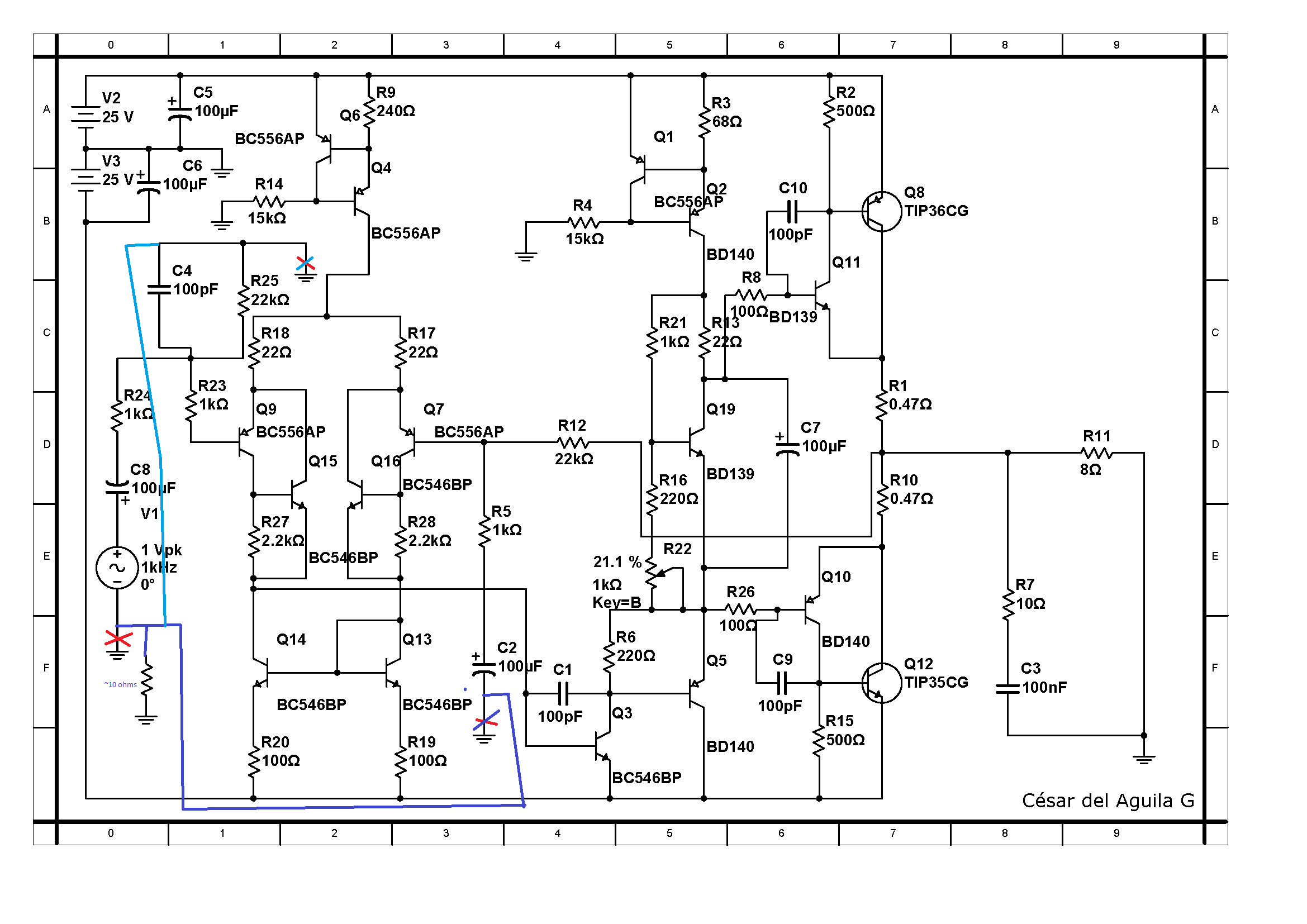
Here is the schematic:

When they are conected start the oscillation, I break the conection of the gnd conection the oscillation stops.
No matter if there is audio signal or not, in booth cases there is oscillation, without signal, and with signal, the oscilation mixes with the audio signal.
I just see it for seconds because it start to get hot, and gives me short time to turn it off.
Here is the schematic:
OK so it's similar to a P3A amplifier. Those wires to the output transistors are far too long. CFP output stages are tricky at the best of times.
Where is Q19 mounted ? It doesnt appear to be in thermal contact with anything. It should be mounted on top of one of the driver transistors.
Where is Q19 mounted ? It doesnt appear to be in thermal contact with anything. It should be mounted on top of one of the driver transistors.
What I meant wasn't whether or not there was signal present -- but whether that ground connection also went somewhere ELSE when it was oscillating ..... to another component or to a signal generator or the like (not whether it had signal output enabled). That can cause a loop situation, with feedback or oscillation. People tend to thing of ground as an absolute equipotential, but it's a current carrying impedance like any other.
I had amplifiers that output junk when the input grounds got connected together via cables to a different component is why I was asking; part of the fix was changing the input stage so that supply/power line noise didn't get conducted on the ground return leads.
I had amplifiers that output junk when the input grounds got connected together via cables to a different component is why I was asking; part of the fix was changing the input stage so that supply/power line noise didn't get conducted on the ground return leads.
I think it is very different in detail, mine doesn't have a bootstrap in the VAS, mine have a CFP everywhere... and long wires as you say for the output power transistors, but they are in this way because are for testing the board. They should be in the board, this is true, but I think it doesn't explain the oscillation.
They will be in the next board.
And Q19 should be in contact with the drivers, I didn't do it this time, with this board to make it faster. But again it doesn't explain the oscillation.
They will be in the next board.
And Q19 should be in contact with the drivers, I didn't do it this time, with this board to make it faster. But again it doesn't explain the oscillation.
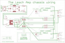
In case the issue is being complicated by a ground shield loop, here is a way to fix it. It avoids external ground currents trying to return via input shield connections (but raising the impedance for such currents without raising the input shield functional impedance). It isn't a bad idea to do this anyway even if it's not part of your problem, many amplifiers get funny noises when they get connected to other gear because of such noise currents.
But Jaycee is right, a CFP stage (you have them both at input and output) can get pretty tricky to keep stable. And those leads to the output transistors are trouble -- if you have to have them long, maybe try twisting just the C and E leads together like that, with the B lead not so tight with the others.
But Jaycee is right, a CFP stage (you have them both at input and output) can get pretty tricky to keep stable. And those leads to the output transistors are trouble -- if you have to have them long, maybe try twisting just the C and E leads together like that, with the B lead not so tight with the others.
Attachments
BTW, in the sketch above, the input shields are not to be directly connected to the chassis (other than through the few-ohm added resistor). They can get get connected together at the far end, though (or to the ground there). The idea is so that only (or at least mostly) signal currents are on the cable shields, not output currents or supply currents or (as is most common) power line noise currents.
What I meant wasn't whether or not there was signal present -- but whether that ground connection also went somewhere ELSE when it was oscillating ..... to another component or to a signal generator or the like (not whether it had signal output enabled). That can cause a loop situation, with feedback or oscillation. People tend to thing of ground as an absolute equipotential, but it's a current carrying impedance like any other.
I had amplifiers that output junk when the input grounds got connected together via cables to a different component is why I was asking; part of the fix was changing the input stage so that supply/power line noise didn't get conducted on the ground return leads.
Only the amplifiers where connected. no signal generator, no preamplifier, even without the oscilloscope, it oscillates. But only one connected, works completely OK.
Only transformer PS, amplifier 1 and amplifier 2.
You have to many individual ground connections /wires.
Combine C6 ground into C5 and take one wire away from C5 to the power common .
Combine C2 ground and R25 /C4 ground into R14 / R4 ground and combine with C5 at the pcb .
Keep the signal ground wire ( the one twisted with the red input wire ) this becomes the signal ground .
Keep the individual zobel ground wire .
This should leave you with:- one wire from C5 to power common
one wire from zobel to power common
one wire ( the one twisted with the red signal wire ) to signal ground .
PS C8 is reversed.
Last edited:
Insulate the trannies first .
Nicely spotted. That will be making the problem even worse too - those heatsinks are effectively antennas directly connected to the transistors collector. The CFP output stage will amplify that a treat.
OK, I made the power transistors shorter.

With more or less the same results. The amplifier with the input grounds connected together oscillates in the same way. BUT when input ground are disconectedfrom each other (and ground) it oscillates, but the oscillation of the next amplifier is very small.

Is it possible to be the only one transistor that is in different shape?

To make the ground changes I will have to make another PCB, so I will make it.
Is it ok to include the PS circuit in the same board or keep it in another board?
Thanks you all
With more or less the same results. The amplifier with the input grounds connected together oscillates in the same way. BUT when input ground are disconectedfrom each other (and ground) it oscillates, but the oscillation of the next amplifier is very small.
Is it possible to be the only one transistor that is in different shape?
To make the ground changes I will have to make another PCB, so I will make it.
Is it ok to include the PS circuit in the same board or keep it in another board?
Thanks you all
- Status
- This old topic is closed. If you want to reopen this topic, contact a moderator using the "Report Post" button.
- Home
- Amplifiers
- Solid State
- Oscillation when connecting the input ground