Brain washing toads and the CIA
"I did not lick the blue frog or I would be dead by now."
Don't try this, at the least it will make you sick. Most of the toad licking
stories are urban legends perpetuated by the gulible "news" media
http://www.lycaeum.org/languages/finnish/acid/data/toad.html
http://members.cox.net/toadvenom/davisWeil.htm
http://www.kingsnake.com/toxinology/amphibian_neurotoxin.html
You Aussies will have to find another use for all those cute cane toads.
I hear they make great pets!
I hear the Dendrobates pumilio really does taste like strawberries though. (humor for you biologist out there)
"I did not lick the blue frog or I would be dead by now."
Don't try this, at the least it will make you sick. Most of the toad licking
stories are urban legends perpetuated by the gulible "news" media
http://www.lycaeum.org/languages/finnish/acid/data/toad.html
http://members.cox.net/toadvenom/davisWeil.htm
http://www.kingsnake.com/toxinology/amphibian_neurotoxin.html
You Aussies will have to find another use for all those cute cane toads.
I hear they make great pets!
I hear the Dendrobates pumilio really does taste like strawberries though.
(humor for you biologist out there)Attachments

Re: Ahhhh...... hard at work at R and D I see!
I guess it depends on how high the output impedance is and how heavy the intended load is. Every device has its output impedance and you can always overload it.
in situations like this, I usually run mine at very high current (and I usually use mosfets in those situations as well) like 20-40ma to mitigate the high output impedance.
But quite honestly we don't usually hook up a speaker to such a circuit, do we?
yeah. I am sure the Pass DIY OpAmp then doesn't work right by your definition. Some kind of "advice",")
peranders said:
Is it good to have a high impedance output in this opamp appplication?
I guess it depends on how high the output impedance is and how heavy the intended load is. Every device has its output impedance and you can always overload it.
in situations like this, I usually run mine at very high current (and I usually use mosfets in those situations as well) like 20-40ma to mitigate the high output impedance.
But quite honestly we don't usually hook up a speaker to such a circuit, do we?
Fred Dieckmann said:Don't try to add a follower output stage. It won't work right,
*Pay -in- Advance
yeah. I am sure the Pass DIY OpAmp then doesn't work right by your definition. Some kind of "advice",
Re: Re: Re: Dual discrete opamp PCB in DIP8
this opamp has Zout=ca. 10ohm/1kHz with gain=1,
and Zout=ca. 30ohm/1kHz with gain=10.(measured)
I don't think that it is so much for one preamp.
Also, most of preamps have resistors with value of ca. 47 ohm at output.
This isn't normal opamp.
Regards
Hi,peranders said:Is it good to have a high impedance output in this opamp appplication?
this opamp has Zout=ca. 10ohm/1kHz with gain=1,
and Zout=ca. 30ohm/1kHz with gain=10.(measured)
I don't think that it is so much for one preamp.
Also, most of preamps have resistors with value of ca. 47 ohm at output.
Why not add an output stage like all normal opamps have??
This isn't normal opamp.
Regards
Re: Discrete Opamp
Sonnya's opamp has 17 transistors.
Elso Kwak said:Not true. See for example Sonnya's design:
Sonnya's opamp has 17 transistors.
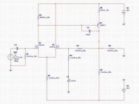
here is my implementation of the nelson amp.
this is an old project (on breadboarded and it worked). I also did a version with a source follower (IRF540) driving a hologen lamp)) as load (sort like a 10w power amp). and it also worked quite well.
the problem with this particular design is its quite large DC offset (100-200mv). I suspect that moamp may have similar problems so having some sort of offset adjustment mechanism may be a must.
this is an old project (on breadboarded and it worked). I also did a version with a source follower (IRF540) driving a hologen lamp
)) as load (sort like a 10w power amp). and it also worked quite well.the problem with this particular design is its quite large DC offset (100-200mv). I suspect that moamp may have similar problems so having some sort of offset adjustment mechanism may be a must.
Attachments
this is what Nelson had to say about the use of a follower as the 3rd stage:
"the follower not only gives a lower output impedance, but makes the performance of the opamp less dependent on the load impedance. if you want to drive a lower impedance load, particularly a speaker, you will want some current gain, and very often you will want the 3rd stage".
http://www.passdiy.com/pdf/diyopamp.pdf
I tend to trust Nelson far more than others, especially those who had tremendous problems correctly capturing a <10 component soft start circuit in the lm317 datasheet.
Thanks for the memories
"yeah. I am sure the Pass DIY OpAmp then doesn't work right by your definition. Some kind of "advice""
It wasn't advice it was satire. Go read the post again....... It was aimed at P-A and I think he understood the point I was trying to make. I guess I have to put warnings in for the humor impaired.
I have no problem with common source or common emitter output stages. One should be aware that the open loop output impedance and open loop gain are determined by the load resistance in parallel
with the feedback resistance. I can't quite grasp your point about Nelson's statement about followers. The circuit under discussion (and similar topology in the Passlass active crossover that inspired all this) has no follower output stage. Trying to leave some wiggle room as to which of the approaches you would take?
Concerns about DC offset in circuit with a monolithic transistor pair with low offset voltage (read data sheets for jfet pairs), in a circuit intended for use at low DC gains, mystifies me and perhaps you can elaborate on the reason for this.
"I tend to trust Nelson far more than others, especially those who had tremendous problems correctly capturing a <10 component soft start circuit in the lm317 datasheet."
Thanks for reminding me of one of the silliest threads ever posted on the forum:
http://www.diyaudio.com/forums/showthread.php?postid=329825#post329825
And the attempt to salvage it to answer the poor guy's origional question:
http://www.diyaudio.com/forums/showthread.php?postid=334669#post334669
I suppose I should be flattered to have my own personal DIYaudio stalker like Mr. Curl. I may hold auditions to get a better class stalker if I am to be in the company of a audio legend like Mr. Curl. Any interested applicants may Email with their qualifications, references, and a sample of their work.
To those concerned about performance
... the master, NP, has indicated somewhere else on this forum that Moamps' circuit is very close to the actual circuit of the XVR1. Major difference is probably that the XVR1 runs at much higher rails. Distortion spectra etc. can be found on the XVR1 manual, freely available from Passlabs. If it's good enough for a commercil high end product it should be good enough for the rest of us
Anyway I'll build a prototype using "lesser" components at hand and check it out againd my OPA2134/BUF634 preamp out buffer combo on headphones. Should be an apples to apples comparison since intended uses and drive capabilities are similar.
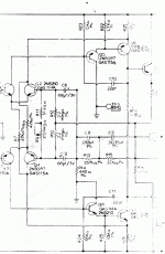
Re: Follower added
Thuis version II with followers added. Sorry for the bad quality, the original is very vague and I am not handy with this scanner.
Elso Kwak said:The question brought up if an output follower of some sort should be appropiate is interesting. James Bongiorno had a similar circuit for the Thaedra phono amp, that is without followers. Later in version II he added followers. I will try to find the schematics.
I doubt the output impedance is high because of feedback in moamps and James' circuit.
Thuis version II with followers added. Sorry for the bad quality, the original is very vague and I am not handy with this scanner.
Attachments
Re: Qualifications
Hi Fred,
Will a sample of KC-8 do?
Qualifications: dirty chemist, poisonous frog collecter, artist in photograpy, inventor of odd circuits, actor in P***films,  imitator of Groman(swe) alias Halojoy etc. etc.[joke]
referencees: descendant of Arnoldi Kwak 1400 A.C.
http://www.quak.info/start.htm
http://www.quak.info/1956445.htm
 [joke]
EditSorry Fred, I cannot react normal to this kind of post of yours.
Fred Dieckmann said:[BAny interested applicants may Email with their qualifications, references, and a sample of their work. [/B]
Hi Fred,
Will a sample of KC-8 do?
Qualifications: dirty chemist, poisonous frog collecter, artist in photograpy, inventor of odd circuits, actor in P***
films, imitator of Groman(swe) alias Halojoy etc. etc.[joke]referencees: descendant of Arnoldi Kwak 1400 A.C.
http://www.quak.info/start.htm
http://www.quak.info/1956445.htm
[joke]EditSorry Fred, I cannot react normal to this kind of post of yours.
Attachments

Fred , love the satire,
I have breadboarded the Pass diy opamps and they work fine.
From my own understanding and prompts from a certain qualified individual, the moamps design is almost identical to that of Passlabs, that latter just run harder with higher rails.
Having worked the diy circuits, the trick in this application appears to be obtaining low gain with low feedback and low output impedance while maintaining the desired properties of an op amp and in just two stages.
IMHO the published moamps circuit fulfills all these aims and without considering greater complexity, there appear few alternatives.
Ian
Re: Thanks for the memories
I have no doubt that one day you would grow into a legend like Mr. Curl.
In the mean time, correctly capturing a simple circuit for simulation would help you greatly in getting there.
Fred Dieckmann said:if I am to be in the company of a audio legend like Mr. Curl.
I have no doubt that one day you would grow into a legend like Mr. Curl.
In the mean time, correctly capturing a simple circuit for simulation would help you greatly in getting there.
 Mr. Wood, please be nice to Mr. Dieckmann
 Where is it?I hear Brian GT has something new that you might want to copy.......... check it out.
Just observing sonnya's design. It's amazing. Without the output stage (just the differential+folded cascode+current mirror) it should have worked fine as a SINGLE STAGE OPAMP, wouldnt it? The gain comes from differential only.
Gain?
I think most of the gain comes from the current mirror loading the folded cascode.....
Hi lunanauw,lumanauw said:
Where is it?
Just observing sonnya's design. It's amazing. Without the output stage (just the differential+folded cascode+current mirror) it should have worked fine as a SINGLE STAGE OPAMP, wouldnt it? The gain comes from differential only.
I think most of the gain comes from the current mirror loading the folded cascode.....
Folded Cascode Design
Hi lumanauw,
Maybe Sonnya's circuit was inspired by the AD817 datasheet or AD797.
Sonnya's circuit has made it to one of Gromans sites:
http://c213-100-118-115.swipnet.se/LM4780/DiscreteOPamp-sonnya.gif
AD817 here:
http://www.analog.com/UploadedFiles/Data_Sheets/289066266ad817.pdf
Hi lumanauw,
Maybe Sonnya's circuit was inspired by the AD817 datasheet or AD797.
Sonnya's circuit has made it to one of Gromans sites:
http://c213-100-118-115.swipnet.se/LM4780/DiscreteOPamp-sonnya.gif
AD817 here:
http://www.analog.com/UploadedFiles/Data_Sheets/289066266ad817.pdf
sigh..................
"Anyway I'll build a prototype using "lesser" components at hand and check it out againd my OPA2134/BUF634 preamp out buffer combo on headphones. Should be an apples to apples comparison since intended uses and drive capabilities are similar."
No it won't...... This circiuit is really designed for driving high (5 K ohm
and above. The fairly low impedance of headphones will knock the open loop gain of the second gain stage way down and severely degrade the performance. This is a preamp circuit, not a headphone amp. The intended uses and drive capabilities could hardly be more different.
Now I'm stepping in it
Fred, can't that be addressed by simply tweaking the output stage? MPSA92 can handle a lot of current, so reducing the PS impedance and increasing the bias should address this, right?
I am not a headphone person though. With most opamps, you are lucky to get something that enjoys driving 600 ohm lines. I wouldn't think the basic topology has a problem with that, but if we are talking 32 ohms I would think a small power amp would be more reasonable.
Output impedance at 10 ohms is very low with respect to most reasonable uses...
EDIT: Perhaps he meant as a replacement for OPA2134, not the BUFxxx part? That seems more reasonable.
Re: Now I'm stepping in it
it wouldn't be difficult to add a follower (as Nelson had suggested) to drive low-impedance load.
Alternatively, you can use a power bjt or mosfet (my preferred method) and turn up the idle current.
in the schematic I had posted, I have used irf9540 as Q3 and it drove real life speakers without any problem.
there is nothing foundamentally there in the topology that prevents this thing from driving low-impedance load.
tiroth said:Output impedance at 10 ohms is very low with respect to most reasonable uses...
it wouldn't be difficult to add a follower (as Nelson had suggested) to drive low-impedance load.
Alternatively, you can use a power bjt or mosfet (my preferred method) and turn up the idle current.
in the schematic I had posted, I have used irf9540 as Q3 and it drove real life speakers without any problem.
there is nothing foundamentally there in the topology that prevents this thing from driving low-impedance load.
- Status
- This old topic is closed. If you want to reopen this topic, contact a moderator using the "Report Post" button.
- Home
- Amplifiers
- Solid State
- Dual discrete opamp PCB in DIP8