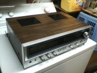
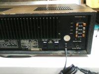
I was given an old Sears/Fisher receiver the other day, its in great physical condition but it won't so much as light up. The Sears P/N is 143 92533800.
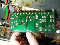
I removed the top and bottom covers and found two blown 6 amp fuses, these are on a small circuit board with the rectifier. The board is badly discolored and one transistor appears to have gotten very hot. The fuses blow instantly on power up.
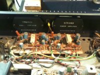
I did an online search for this model and came up empty as far as a circuit diagram or manual. It uses twin STK082 amp chips so I'm guessing its around 32 wpc. This also leads me to believe this was likely built by Sanyo for Fisher.
Does any one have any pointers as to how to go about fixing this thing?
I removed the top and bottom covers and found two blown 6 amp fuses, these are on a small circuit board with the rectifier. The board is badly discolored and one transistor appears to have gotten very hot. The fuses blow instantly on power up.
I did an online search for this model and came up empty as far as a circuit diagram or manual. It uses twin STK082 amp chips so I'm guessing its around 32 wpc. This also leads me to believe this was likely built by Sanyo for Fisher.
Does any one have any pointers as to how to go about fixing this thing?
Attachments
Considering the blown fuses, its most likely that one or both STK082 hybrid power amp. modules has also fried. These are replaceable with refurbished (very dicey), copied versions (soewhat dicey), pulls (maybe good if the source properly tested them) or NOS parts (no, don't believe it).
A good, economical and DIY friendly alternative is to remove the hybrids and the rest of the damaged power amplifier section and replace with a current Chipamp design such as LM3886 based modules, kits of parts or just the PCBs. These are cheap, plentiful and work just fine as long as the scant information you get with them is sufficient for correct connections and you have an adequate power supply and heatsinks to suit the same power output as previous, which you'll need to control by the maximum amount of input signal fed to it. If you aren't careful with this, the amplifiers may deliver too much and the little power supply overloads and the fuses blow, before the inbuilt limiting of the chipamp can kick in.
Before buying, it might be wise to remove the power connections from the power supply rectifier and smoothing caps to the amplifier board and test that the power supply is functional when its fuses are replaced and no further problems are apparent. This should be the case, provided the rectifier is Ok, caps are fair and there are no shorts such as you get when someone isn't careful as they shove things that don't work, back together again.
That done, measure the main power supply voltages with respect to ground and check they there is something like +/- 25V or, since I can only see a single ballast resistor for each channel, it could have just a single voltage supply of about 50V. A single supply would also mean that the outputs to the speakers are via a large capacitor. Since all fuses, perhaps including output fuses, seem to be on a separate board, any output caps could be there.
Could the STK chip cause the power supply board to fry like this?
I was thinking that maybe something failed in the power supply since the fuses are between the two wires from the transformer and the rectifier. the two other lower amperage, (1a & 4a) fuses seem to feed other boards The two fuses that are blown, are 6 amp slow blow AGC type. I tried replacing the fuses and new one's pop instantly. I powered it up with a variac slowly, the fuses popped at about 30v to the power cord. I unwound the wires to the amp board. Looking at the circuit board traces it looks like the two 6 A slow blow fuses are between the transformer wires and the rectifier. Testing the rectifier as if it were four diodes, I get a short between two legs, 0 ohms in both directions between the - marked leg and one 'AC' marked leg. in both directions.
Could the rectifier have crapped out and caused the transistor to overheat or vise versa? The transistor appears to have gotten so hot it looks burnt, but looking at the burn pattern I can't tell if the heat came from the transistor or the wire wound resistors ahead of it. That's a lot of heat there that apparently happened for a long time before the fuses blew.
What gets me is that this seems to have shut off all power, with the two blown 6a fuses, no power reaches any other part of the unit.
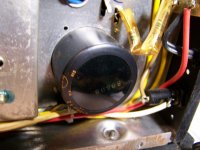
The two 330uF caps on the p/s board are the largest normal looking caps in the whole receiver. There is a 3 pin capacitor in one corner that sits recessed into the chassis with 6 wires on it. There are are few numbers on it and some Japanese writing but no values I can see other than one marking reading 85°C.
Am I correct in thinking that this board is what supplies power to the rest of the receiver?
The two largest wires on the output side of the transformer appear to go directly to the pair of 6A fuses, then from the fuses to the rectifier.
The are a pair 1.5a speaker fuses on the amplifier board that appear to go out to the speaker terminals, both of those are good. There are two .5A fuses on the preamp board up front, those two are also okay.
I do have a few Sanyo built parts receivers, several of which use the same STK chips that work which I can borrow parts from for testing.
There is no sign of heat or burnt pins on either chips, the blurred lettering on the left chip is from me touching it, they both have a coating of something sticky, when I touched the chip, the paint wiped right off. I had pulled both chips back to add some fresh heat sink compound but the original grease was still soft. I wiped them off and replaced the grease anyhow.
I was thinking that maybe something failed in the power supply since the fuses are between the two wires from the transformer and the rectifier. the two other lower amperage, (1a & 4a) fuses seem to feed other boards The two fuses that are blown, are 6 amp slow blow AGC type. I tried replacing the fuses and new one's pop instantly. I powered it up with a variac slowly, the fuses popped at about 30v to the power cord. I unwound the wires to the amp board. Looking at the circuit board traces it looks like the two 6 A slow blow fuses are between the transformer wires and the rectifier. Testing the rectifier as if it were four diodes, I get a short between two legs, 0 ohms in both directions between the - marked leg and one 'AC' marked leg. in both directions.
Could the rectifier have crapped out and caused the transistor to overheat or vise versa? The transistor appears to have gotten so hot it looks burnt, but looking at the burn pattern I can't tell if the heat came from the transistor or the wire wound resistors ahead of it. That's a lot of heat there that apparently happened for a long time before the fuses blew.
What gets me is that this seems to have shut off all power, with the two blown 6a fuses, no power reaches any other part of the unit.
The two 330uF caps on the p/s board are the largest normal looking caps in the whole receiver. There is a 3 pin capacitor in one corner that sits recessed into the chassis with 6 wires on it. There are are few numbers on it and some Japanese writing but no values I can see other than one marking reading 85°C.
Am I correct in thinking that this board is what supplies power to the rest of the receiver?
The two largest wires on the output side of the transformer appear to go directly to the pair of 6A fuses, then from the fuses to the rectifier.
The are a pair 1.5a speaker fuses on the amplifier board that appear to go out to the speaker terminals, both of those are good. There are two .5A fuses on the preamp board up front, those two are also okay.
I do have a few Sanyo built parts receivers, several of which use the same STK chips that work which I can borrow parts from for testing.
There is no sign of heat or burnt pins on either chips, the blurred lettering on the left chip is from me touching it, they both have a coating of something sticky, when I touched the chip, the paint wiped right off. I had pulled both chips back to add some fresh heat sink compound but the original grease was still soft. I wiped them off and replaced the grease anyhow.
I haven't worked on one these Fisher Sanyo models, just a few that were superficially alike and from the same era, which means I can only guess about the specific details from appearance. Anyway, the bridge rectifier would only have blown when there was a heavy load on the DC supply, specifically the main power supply which powers the audio modules and possibly other circuits too. That's why the power amplifier(s) would be suspect if the rectifier had blown. You'd then have to check the leads coming from the transformer and look for other rectifiers that might power the other circuits such as the tuner, preamp and front panel lighting (this is often just AC powered) to be sure how many windings and power supplies there were. The power for these minor circuits wont be much, so if there was a short on any of the small power supplies, the winding supplying it may just burn out without affecting the other supplies or blowing the mains fuse. However, this amount of burn mark, looks like there might have been a serious fault and a large flash that may have taken out the transformer primary winding and more. That would certainly leave you with no function at all. You can test the transformer windings for continuity by measuring resistance, winding by winding, after you have disconnected at least one end of a winding to ensure nothing else is messing with your measurement. Check for connections with other windings, in case there are actually tappings rather than separate windings. You should read only about 20 ohms for the 110V primary winding and less for the amplifier supply secondary winding(s).
Note, with any DC supply big enough to power 2 X 30W amplifiers , there must be at least 3,300 uF caps somewhere, or they've been removed.
Its better at this point to just check winding continuity unpowered, rather than power up again and risk more damage or your own safety. If your measurements lead you to think the transformer has indeed failed, you might want to consider a complete redesign and build because you won't be able to directly match multiple secondary voltages with any stock transformer.
Last edited:
Freisforme
Before blowing more things.. Can You identify the PA rail Supply wires ? Follow the datasheet corresponding pins to the board connectors.
Disconnect them from the Amp and try new fuses. If they blow agian, You know where the problem is. Pray the STKs are ok.
Regarding the caps.. Perhaps someone confused 330 with 3300. I'm sure it hummed like mad...if ... working...
Regarding the Sticky amps... CocaCola, Beer You name it perhaps.
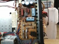
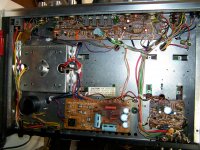
What's all that black on the power supply board? Is it just from heat from the power resistors or is something blown up there? Looks almost like a disk ceramic cap blown up, hard to tell from the photo though. Looks a lot like lightning damage.
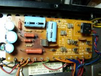
All that black is in front of the D330 transistor, the transistor is badly discolored as is the wire wound resistor facing it. The burn and discoloration goes right through the board and it left a burnt mark on the metal chassis above it as well.
I don't think its lightning damage, it more looks like an area that's been exposed to a lot of heat over time. A quick flash of heat wouldn't 'cook' the circuit board so deeply. The transistor looks like it was in a fire for a hour. The aluminum tab on it was burnt and turned colors from heat, but not melted and there is no other physical damage to the transistor.
All three legs of the transistor are shorted together, in all directions at all times.
I don't have any manual or diagrams for this, all I can do is try and follow the traces on the circuit board and read the markings on components. I did an online search for this model but didn't find anything. A few were close but differed greatly in the power supply area.
Several of the caps on the burnt board have something leaking from them, it looks like brown tar. Those caps have no capacitance and only a few ohms of resistance. Only one of the 330uF caps tests ok.
The only larger cap is a single three terminal can in one corner of the unit, I have no clue as to what its specs are as its not marked in anything but Asian script.
If one or both of the STK chips were creating an extreme load like this, enough to burn through several components, wouldn't there be some sort of sign or heat on or around the chip itself?
The heat damage on the power supply board is very localized. I would think that if a load high enough to produce enough heat to make this kind of burn mark was present in the amp board, it would have melted wires or shown some signs of burning elsewhere?
The burn mark looks as if someone held a flame in that one spot for a long time. the surface of the surrounding board is burnt like firewood, but the trace on the other side is unhurt. It almost looks like the transistor got red hot.
The two ceramic caps both check out fine, I removed both and tested them off the board. The back side of the board shows no sign of damage, but the unprinted side is damaged to the point there's ash and a burnt layer present.
Usually when I see a lightning hit board there's burn through and missing pins, I don't have that here. The hottest point appears to have been the transistor and/or one of the larger resistors.
I'll see if I can check the transformer to see if I can detect any damage. I sort of doubt it because the two leads that area connected to this board still supply power to the fuses since it blew them right away once they were replaced. Every wire from the transformer goes to this board. A few go to unused pins, with no connection to any components on the board, just pins.
If you look at the pic of the burnt board, all of the heavier insulated wires on the right side go to the secondary side of the transformer, the two black wires are the primary side wires, also connected to one receptacle on the rear of the unit. The red and blue wires are the higher voltage, orange and blue gives half voltage. No power is making past this board with the fuses blown, with the fuses replaced, with low voltage applied, I can follow the voltage to the rectifier, where it stops, nothing beyond it. AC volts go in, nothing comes out, as the volts increase, it gets warm and pops the fuse pretty fast. I'm thinking I need to start with fixing the obvious damage first, a handful of new caps, a new transistor, a diode, and probably a new rectifier. Then see what happens as I bring up the voltage and try to get it to power up. If it needs amp chips, I guess I'll borrow a pair from another unit for now.
I wish I had a wiring diagram for this thing, at least then I'd have a better idea of the power flow. Does anyone have a pinout chart for the STK082 chips?
I took a few better pics of the power supply board and did some testing.
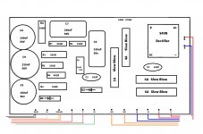
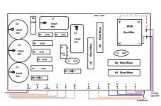
I also drew up a diagram of the front of the board with the marked values. The values marked on this diagram are what is marked on each component along with the location number marked on the board itself.
I removed both STK chips and temporarily installed each one in another (LXI) receiver and both work perfectly.
While looking at the p/s board, I noticed that the red and blue wires next to the rectifier, which come out of the transformer secondary side, connect to the + and - terminals of the rectifier? These wires become live when the switch is turned on even without any fuses on installed on this board. All of the six heavier gauge wires on the rigt side of this board go into a hole in the transformer casing, the other six go from this board to various other boards on the unit and ground.
With the switch on, there is voltage at each of the six heavier wires, coming from the transformer, but nothing leaving the board with or without the fuses in place. With the 1, 4, and 6a fuses installed. I used a dim bulb tester to test for a short here first. This remains even if I remove the six smaller gauge wires to the other boards.
I tested each component, five of the resistors read less than half of their rated ohms, and only one capacitor functions at all. The one 330uF cap nearest the transistor is a dead short with .007Ω resistance and zero capacitance, I got the same from the single 220uF cap, and C8 showed twice the capacitance and a very low ESR reading.
R4 = 180Ω
R3 = 549Ω
R5 = 79Ω
R2 = 102Ω
R7 = 1000Ω
R1 = 320Ω
There is continuity between the + terminal and upper right AC terminal on the rectifier in both directions.
All three legs of the transistor, (Q1), are shorted together with zero resistance with it removed from the board.
I have several meters to test with, I double checked with both of my other meters after getting the way off resistor readings but all my meters agree.
There is one other cap on the preamp board that's leaking some sort of gooey oil also. I can't tell if its an adhesive they used or if its electrolyte from inside the cap leaking.
The extreme heat definitely came from the 330D transistor, its the most damaged by heat and the cap behind it is slightly melted too.
I'm just not sure at this point what the cause was? The damage seams to be limited strictly to this board. The STK's work fine in another receiver, and the short remains even with the other boards disconnected.
It does seem that all power flows through this board first, every wire coming from the transformer on the secondary side goes to this board first and no where else. Incoming power, 120vac comes from the power cord, through the fuse, to the power switch, then to the transformer and to one rear outlet, the second rear outlet is connected directly to the power cord.
I also included a wider view pic showing the single large cap in the corner, it has three posts on top and six wires on it. I can't read the value on it. Its about 4" tall and 2.1" in diameter
Attachments
The rectifier was tested out of circuit, there's no doubt its bad. The same with the transistor. It reads zero ohms between all three pins.
What surprised me the most is how far off the resistors are, none of the larger power resistors are anywhere close to what they're marked.
I'm also not clear on why the two wires on the dc legs of the rectifier go back into the transformer? The two red wires each feed one of the 6A fuses through pins 1 & 2, the fuses are connected through the traces to the rectifier on the ac side. The small ceramic cap is across the two AC feeds on the rectifier. These parts do not connect to the rest of the board at all, the rectifier, the two 6a fuses, and the one small cap are separated. The power comes in from wires that come from the transformer, and the two DC wires go over to the big single capacitor in the corner.
I have a good used rectifier, but I'm not seeing what caused this yet. The rectifier isn't directly related to the transistor that overheated so bad, and both STK chips test out fine and work. I'm assuming the extreme heat from the transistor is the cause of the resistors being so far off, and maybe even the caps around it leaking. But what caused the transistor to get so hot?
I did figure out how to test the big capacitor, one pin is common, if I test it in two halves, I get 6750uf and 6737uf per side. The markings on it are in Japanese with only the 85°C marking being in normal text.
Is it possible for an STK chip to test out fine cold and act up hot? Both of these played fine in an LXI receiver I have here but I only put them in that circuit as temporary installation, soldered just enough to make contact with only a pair of spring clamps to ground the heat sinks. I let it play for about 3 or 4 minutes tops.
In your latest pics, it's pretty clear that those large red resistors and the transistor have been running hot for a long time and it wasn't unexpected, judging by their spacing from the board. The transistor appears to be a regulator for a low voltage supply such as for the preamp, tuner, maybe even the lamps. As those caps have been replaced, it's harder to know what the actual cause of the transistor failure was but you'd think it would most likely be downstream, not in the power amplifier.
What makes you say the caps were replaced? I've not yet changed any parts, the pics were all taken before I unsoldered anything.
As to parts on hand, I have an identical rectifier here, not sure what it came from but it tests good. The transistor, caps and larger resistors will have to be ordered.
I also found a box of new old STK modules here, but no 082 chips, but I do have a pair of brand new STK086 Sanyo OEM chips here. (I bought a bunch of parts at an auction about 20 years ago, those are from that lot of parts). I'm not sure how to go about figuring out what the replacement resistors should be, I have values but not wattage.
The LXI receiver I tested the STK082 chips in has cement type resistors on its power supply board.
The red resistors don't show the heat damage that the transistor does, the cap right next to it is actually melted. If it were the red resistors making the heat, the transistor would have shielded the cap or I'd see an outline of the transistor shape on the side of the cap. The transistor seems to be the hot item on the board. I don't doubt that the resistors also got hot but I don't think they were the source of the heat.
What gets me is that none of the thin wires leading from this board are burn, they can't be more than 20ga. at best.
Caps C9, and C6 are shorted, C9 is a dead short with the neg. side connected to chassis ground via the black wire on pin 12.
It seems like there was a lot of heat for a long time before it blew the fuses?
All the fuses were correct and nothing in this thing appears to have been repaired before. The caps in this are unbranded, but they match every cap in this thing except for two orange colored caps on the amp board and the big filter cap in the corner. Do they not look correct for one of these?
The few replacements I've got on hand are Nippon branded. I'll have to order a few of the values I need plus the transistor and those wire wound resistors.
I assumed the small caps on the power board were replaced because 30+ years ago, the printing on Japanese caps was not as sharp as we see now. I could well be wrong and admittedly, those on the amplifier board look quite similar, under the dust. I certainly wouldn't expect them to still have low ESR after that time, though.
Looking at the pic of the power board, there is a darkened area behind most of the red caps. No manufacturer fits large resistors unless they need to dissipate heat and larger sizes are necessary to give the resistor more power rating and extra surface area to dissipate more heat. Phenolic type boards like that, all darken over time but heat accelerates it. It's not necessarily charring, which is plain to see with epoxy/glass fibre boards, but a gradual darkening of the phenolic type resin itself, sped up by heat. I can say this because it was once my job to research and develop replacement materials.
It won't take much current, certainly not as much as needed to heat or burn small wiring, to overheat the regulator transistor. When there is no heatsink, it can only supply a fraction of its rated maximum power. Many Japanese designed TVs used numbers of such simple regs and even with small heatsinks fitted, they normally were roasting. A fault like a short downstream could easily overload the transistor and cause it to overheat and fail so as I wrote previously, you should check loads on power supplies first, just by disconnecting them if you don't have gear like a bench power supply to test the load current independently.
The only markings on these blue caps is the value and the letters CE-W in tiny print.
The board is charred on the surface in front of that transistor, enough so that the top layer is gone. I wiped off the char on the board and some of the components with some cleaner so I could read what they were. I don't think the board is damaged enough to be an issue though. Until I get hold of the new parts for this board, I can't do much more testing without any equipment here. The 6A fuses both blow even with all the board's outputs disconnected, but I was figuring that was due to the shorted transistor or rectifier. However, after following the traces on the back of this board, the rectifier and fuses are not directly connected to the rest of this board, they lead only to the dual 4700uF cap on the other side of the chassis. The shorted transistor and caps aren't in the same circuit as the blown fuses. Only the rectifier, larger cap, and eventually the main amp are.
I don't see any burnt damage or signs of heat on the main board, but if I remove both the STK chips the fuses survive me applying power and the dim bulb tester doesn't light the instant I turn on the switch. The pinout of the amps gives me voltages to look for but since I can't power them up in this board, I can't do that. All I can do is check for resistance between pins. Plus, both amps played fine in the other receiver.
What piece of equipment do I need here?
I have a good volt/ohm meter, several 'component testers, two capacitor testers, but no oscilloscope and no bench power supply. I do have several variacs though plus a few good 12v power supplies for working on car radios and amps.
My area of expertise is automotive and heavy equipment, as well as welding and steel fabrication.
I'm sure there's equipment I need to find to be able to fix this sort of thing and sooner or later I'll figure out what I need but good equipment is expensive and hard to come by used in good condition.
I would have just dropped this thing off to a repair shop to have it looked at but we don't have any who will touch older equipment. The one shop that will work on it charges $200 minimum to look at it, plus repairs. I don't see an old receiver like this being worth more than about a $100 or so, maybe less. I'm only looking to fix this one because it belonged to friend who recently passed away.
What I'm finding now is that the parts are hard to come by, the list of parts for the power supply board are over $100 alone when I figure in shipping. Most places I've checked with only have one or two items, so I'm looking at shipping from 10 different sources and many items come only in packs of 5 or more. For example, a TIP31C transistor is only $1.29 each, they come in packs of two, so I'm looking at $2.58, plus $7.99. Shipping for the one transistor I need. That source doesn't have the caps I need. So far the eight places I checked for the various caps don't have more than one of each of the values I need per source. The one that lists the 330uF 50v axial caps doesn't carry the 100uF or 220uF values. So for just the caps, I'm looking at $8 shipping times three from three different sources, plus the price of the caps, which works out to be about $7 for each value for packs of 6 of each. So the cost of the caps in the end will be almost $45 for the 6 caps I do need with some extras left over. Then the resistors that I need will be another search, so far I've not figured out who they will have to come from. What it boils down to is that to get good quality parts that I know aren't from China, I have to hunt all over the place. The three closest suppliers all carry only cheap unbranded parts. A few are known for carrying Chinese knockoffs. I've also been having issues finding TO-3 type transistors for an amp I'm trying to fix, so far all I've gotten is Chinese knockoffs that don't work or don't last.
I have some of the caps needed, but not all, but the caps I've got are pretty old, probably from the 1980's so they're likely not in much better condition due to time.
If I'm going to put new parts in something I want to use fresh, new parts.
In the right picture on the capacitor top upside down says 4700uF x 2. So it's (are) the main rail capacitors. Six wires makes sense. Two incoming + & - from rectifier, two outgoing to amp, and two for star grounding ?? Red1 and 2 on the left board (6A fuses) would go to this Capacitor and from there to the amp...No ! based on the chassis picture, the two red come from the transformer enter the fuses, get rectified and the the red and blue (should be + & - rail voltage ) goes to the large capacitor... and that black wire would be Your Ground. Check if these 3 wires, red, blue and black go to the capacitor. They Must !
Last edited:
The two small black wires go to chassis ground right next to the board, soldered to a tab. The middle wires on the big cap go to ground via a lug bolted to the heatsink between the two STK modules.
The red and blue wire leaving the rectifier go to the outer terminals on the 4700uF cap. The two red wires come from the transformer, go through the fuses, then to the rectifier. The heavier red and blue wires are what leave the power board and go to the capacitor.
The red and blue wire leaving the rectifier go to the outer terminals on the 4700uF cap. The two red wires come from the transformer, go through the fuses, then to the rectifier. The heavier red and blue wires are what leave the power board and go to the capacitor.
These Sanyo and similar budget models go for as low as $5 on Ebay in the US. Don't spend money on parts to fix something, probably with great difficulty, time and a need for more skills and equipment, that will likely be simpler and inexpensive to replace with a working one.......What I'm finding now is that the parts are hard to come by, the list of parts for the power supply board are over $100 alone when I figure in shipping. Most places I've checked with only have one or two items, so I'm looking at shipping from 10 different sources and many items come only in packs of 5 or more. For example, a TIP31C transistor is only $1.29 each, they come in packs of two, so I'm looking at $2.58, plus $7.99. Shipping for the one transistor I need. That source doesn't have the caps I need. So far the eight places I checked for the various caps don't have more than one of each of the values I need per source. The one that lists the 330uF 50v axial caps doesn't carry the 100uF or 220uF values. So for just the caps, I'm looking at $8 shipping times three from three different sources, plus the price of the caps, which works out to be about $7 for each value for packs of 6 of each. So the cost of the caps in the end will be almost $45 for the 6 caps I do need with some extras left over. Then the resistors that I need will be another search, so far I've not figured out who they will have to come from.
My father had an obsession with restoring what he considered was valuable and spent most his spare time over 50 years, struggling with repairs of old consumer electronics gear which he didn't need and had few buyers or takers for. A waste of a lifetime and 2 sheds full of scrap that I had to pay an awful lot to dispose of, at the end.
I like to repair stuff too but when I look at the costs to me, whether the parts originate in China or other countries, the retail mark-ups are prohibitive, as your costs indicate. You can also be fairly sure that major brand, consumer-use components are virtually all Asian imports now, either as OEM or branded as US or European product anyway. You'll find you are on hiding to nothing buying parts as a supporter of local manufacturers and retailers. Just consider where the largest semiconductor manufacturing plants are located now and the freight subsidies offered, for a more realistic viewpoint.
A better option when you have a list that is long enough to qualify for cheap or free freight, would be the big distros, Digi-key and Mouser. They have everything in one place - too much to choose from really. Many members here use either when there is local representation and currency options.
I agree, I highly doubt any of the parts available will be from anywhere besides China. I'm running into that same problem with two other amps I've got here and one receiver. Most of the parts I need come up as no longer available at either of the two sources you mentioned, with eBay being the only option left. From what I've seen and heard, that last option is almost certain to turn up counterfeit or junk parts.
I don't need any receiver, I've probably got 20 working one's in the closet but I hate to just toss something out that should be an inexpensive fix.
Both of the two companies you listed show only one or two of the parts I need, and they come up blank for the rest. It might just be a matter of me not knowing the correct substitutes to use as well. Fixing any of these old receivers and amps is rarely profitable but I do it in my spare time. I don't mind spending $20-$30 to fix something that I can make 100% again. But with suspect or counterfeit parts, it will likely never been 100% again. What bothers me the most is that these Chinese knock off parts are turning up at reputable shops who swear they're selling the real thing. There's one about an hour from here like that. They've been in business for decades selling parts and speakers, they carry their own rebadged brands so you can't see where they got the parts from. I bought a lot of TO-3 transistors there last summer for an old amp and out of 20 transistors, only 5 were good right out of the bag. They swear up and down they are 'genuine' Motorola transistors.
I guess the fact that his source for new old stock Motorola transistors is unlimited doesn't set off any alarm bells? These things were scarce 20 years ago, now all of a sudden he's got as many as I want.
- Status
- This old topic is closed. If you want to reopen this topic, contact a moderator using the "Report Post" button.
- Home
- Amplifiers
- Solid State
- Sears by Fisher Receiver won't power up