Pass DIY Addict
Joined 2000
Paid Member
Axial caps will be harder to find. As for more traditional radial caps, you should be able to spread the legs enough to reach the holes. You may need to add additional length to the legs of some caps (just solder on some additional solid core wire, and wrap in heat shrink) in order to fit back onto the board.
Start with the caps in the PSU first, then move on to other boards. If you have a schematic, it will help you identify the caps you need. Try searching on the model number of the amp - something usually turns up. Strange that they don't all have uF and voltage ratings stamped on them.
Some of the larger caps are likely to be glued down. If you see a thick, brown, sticky (or dried and hard) paste between the cap and the board, it is likely to be an adhesive of some sort. This is common with large PSU caps, less common with small caps on the signal boards. Over time, the electrolytic fluid leaks from caps which causes them to dry out and form a short. Sometimes, this fluid leaves a visible residue on the PCB, sometimes not. If you find it, it is a sure sign you caps are old and dry. Absence of this evidence is not evidence that a cap is still good...
As for uF value of caps, there are tables published of "standard" cap values. Choose the next higher value that you can find. Mouser and Digikey are usually my sources - search on "electrolytic capacitors."
Axial caps will be harder to find. As for more traditional radial caps, you should be able to spread the legs enough to reach the holes. You may need to add additional length to the legs of some caps (just solder on some additional solid core wire, and wrap in heat shrink) in order to fit back onto the board.
Start with the caps in the PSU first, then move on to other boards. If you have a schematic, it will help you identify the caps you need. Try searching on the model number of the amp - something usually turns up. Strange that they don't all have uF and voltage ratings stamped on them.
Some of the larger caps are likely to be glued down. If you see a thick, brown, sticky (or dried and hard) paste between the cap and the board, it is likely to be an adhesive of some sort. This is common with large PSU caps, less common with small caps on the signal boards. Over time, the electrolytic fluid leaks from caps which causes them to dry out and form a short. Sometimes, this fluid leaves a visible residue on the PCB, sometimes not. If you find it, it is a sure sign you caps are old and dry. Absence of this evidence is not evidence that a cap is still good...
As for uF value of caps, there are tables published of "standard" cap values. Choose the next higher value that you can find. Mouser and Digikey are usually my sources - search on "electrolytic capacitors."
I don't have a schematic or parts list for this, I've not been able to find one.
For some reason this model don't show up anywhere. (143.92533800), its a Sears catalog number not a Fisher model number. It says Sears Audio by Fisher on it. Most of the caps are Sanyo or Rubycon. Most other parts are marked Sanyo as well. I found a few similar models listed but those are nothing like this one inside. I came here after not being able to find anything on it, with no specs or schematic, all I have to go on is other's experience.
Pass DIY Addict
Joined 2000
Paid Member
Hmmm... Are there any part numbers on the circuit boards? I would try searching on these or on the number printed on the amp IC that is attached to the sinks. I wish I could think of something that would be of more help...
I had a similar unit many years ago, but it is long gone now. It featured a new-fangled technology called "quadraphonic"") and had this really cool "joy stick" speaker balancing mechanism. Wish I still had that one...
and had this really cool "joy stick" speaker balancing mechanism. Wish I still had that one...
I had a similar unit many years ago, but it is long gone now. It featured a new-fangled technology called "quadraphonic"
and had this really cool "joy stick" speaker balancing mechanism. Wish I still had that one...That joy stick model is what I keep finding, those are pretty common. It seems everything from this era was quadraphonic vs. 2 channel stereo.
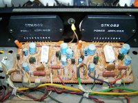
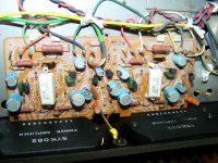
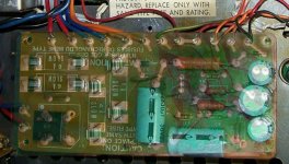
The amps are STK082, the boards have some ink stamped numbers but no part numbers that I see so far. The caps without values are those marked CE W 129 on them in the pic, the oposite side has only the black stripe and the end of what looks like uF near the top but no numbers. There are four of these, two for each channel or amp chip.
The tuner board has the caps that read 1/16 over and over again on two sides.
A few are marked 25 25 and 47 47, those are Sanyo branded caps. A few of the orange caps are marked only with the temp rating and the letter M over and over again, those are on the preamp board.
Attachments
Pass DIY Addict
Joined 2000
Paid Member
OK, let's focus on one thing at a time. I would recommend starting with the power supply board. Given its color, I would replace everything on it (the rectifier may still be good - it is easy to test) and check the back of the board to make sure the traces are still intact. If they aren't, just solder a wire across the top of the break. I'm not sure what that transistor is, any voltage regulator should have a heatsink attached to it... If you get the power supply up and running again, it is possible the rest of the amp will work.
I am also surprised that those 330uF caps are the largest ones in the amp... I would expect to find something on the order of 10,000 - 15,000uF caps to power the amp boards. I wish I had poked around inside of my old amp a bit more.
I am also surprised that those 330uF caps are the largest ones in the amp... I would expect to find something on the order of 10,000 - 15,000uF caps to power the amp boards. I wish I had poked around inside of my old amp a bit more.
It's in #11........I am also surprised that those 330uF caps are the largest ones in the amp... I would expect to find something on the order of 10,000 - 15,000uF caps to power the amp boards.....
I did figure out how to test the big capacitor, one pin is common, if I test it in two halves, I get 6750uf and 6737uf per side. The markings on it are in Japanese with only the 85°C marking being in normal text.
Pass DIY Addict
Joined 2000
Paid Member
Ah - missed the details on these caps, thank you. My guess is that all of the heat on the PSU was caused by caps starting to dry out and short. This starts as just a little bit of resistance within the caps and the resistance grows slowly (sometimes quickly) over time. As resistance increases, heat also increases. This heats up the resistors and the transistor. This heat further accelerates the drying of the caps, which in turn, increases their resistance further. The resistance begins to place greater strain on the rectifier as well. Pretty soon, the entire PSU is a big heat source and things begin to fail from there. If you are lucky, the damage is confined to the PSU board. Shorted caps will typically keep the PSU voltage from traveling further into the amp.
The caps that measure ~6800uF can be replaced with 10,000uF caps without any trouble. I would disconnect the PSU from the rest of the amp, replace caps, resistors, bridge, bring the power back up, then take some measurements to see what you get.
The caps that measure ~6800uF can be replaced with 10,000uF caps without any trouble. I would disconnect the PSU from the rest of the amp, replace caps, resistors, bridge, bring the power back up, then take some measurements to see what you get.
Oddly enough the only part of the PS board that's not working at all is the rectifier and 6amp fuse end, the rest is still working to some degree. The transistor is shorted but I'm somehow getting voltage out of the other leads. The two fuses blow instantly, even with the board separated from the rest of the circuits. The rectifier is bad across two pins, I have one I think will work from another junk Sanyo built unit. It looks like the same part and number and that one powers up. The rectifier and two 6a fuses are separate from the rest of the board, they take power from the transformer on the first two pins, then send it down to the double pole capacitor that supplies the amp board.
I changed out the rectifier, hooked up only the amp board and only one fuse blows now. The rectifier is good, but one fuse still pops. Its the fuse connected to the positive side of the rectifier. If I remove the wires from the 6800uF cap the fuse survives. the cap reads well within specs, its a dual pole style cap recessed into the board so its not going to be an easy find unless I retro fit two caps but space may be an issue. I don't think the cap is the issue. I removed all four wires from the cap to the amp board, and reconnected them one at a time. The fuse blows when I connect the blue wire closest to the cap, or to the far left of the amp board. Leaving that wire off lets the fuses survive and the voltage jumps up to almost double the 14.7v I had with it connected on the other leads. With the blue wire off, I get almost 30 volts on both sides of the cap.
Also, I just looked back to a former post here I miss typed the value of the main cap as 6750 and 6737, when I should have typed 4750 and 4737. I get an ESR on each side of .13 and .12 on each side. To me that looks acceptable for now since the cap is marked 2x4700. The markings are noticeable in the blown up pic but near impossible to see by eye for some reason.
Pass DIY Addict
Joined 2000
Paid Member
Ok, just read through everything again. Let's focus on simplifying the approach and working as methodically as possible. This approach will likely result in replacing a few things along the way that may not need replacing, but will allow you to eliminate variables and cross things off the potential problem list as you go - thus building confidence.
Start with the transformer: There are three pairs of secondaries (red, blue, orange). Disconnect all of them. Measure the resistance of each colored secondary pair without any power applied (red to red, blue to blue, orange to orange). These should measure a few ohms, say 5 to 20 or so - each pair will have a different resistance reading. Measure resistance between secondaries (red to blue, blue to orange, orange to red) - these should measure as open - infinite resistance. I don't suspect any problems here, but it is always worthwhile to remove them from suspicion from old equipment that has been blowing fuses. Before you reconnect these wires, get an AC voltage reading on each secondary pair by powering up with all secondaries disconnected from the circuit board, being careful to keep them separated. This might serve as a good reference for the future.
It is odd that both legs of the red secondary pair are fused - 12A in total is a lot of juice. You said you already replaced the rectifier, so I trust this part. If one of your 6A fuses pops when you reconnect the twisted red/blue pair that goes to the large cap in the corner, then this cap is dead, too (or at least half of it is). Replacing this will be most difficult due to physical dimensions, but I would suggest something that is close to 10,000uF will be fine. With the voltage reading on the red secondary pair * 1.4 (rectification multiplier) + another 5-10v for a margin of safety will provide a good starting point for the voltage rating on this cap. The ceramic disk cap closest to the bridge rectifier is likely good, but also easy to replace - it is a snubber for the rectifier to keep the noise down.
I'm not entirely sure what to make of the blue and orange secondary pairs - they power the "rest" of the amp as already pointed out: preamp, tuner, lights, etc. The voltage present here should clearly be smaller than that of the red secondaries. I see D5, which I would also replace with a generic 1-2A 100V diode - this likely provides single phase rectification for the other boards. The part that confuses me is you have two secondaries (blue, orange) and I only see one obvious doide- D5. I would expect both of these AC secondaries to be rectified to DC on this board to keep AC noise out of the rest of the receiver. Q1 looks like a voltage regulator (perhaps a dual diode in a single package?). It clearly needs to be replaced - whatever markings on it that are readable should help identify what it is. If Q1 is directly connected to D5 (check traces on back of PCB), then it is a voltage regulator (highly likely given its proximity to resistors and caps). The challenge here is knowing what level of voltage it provides. Any readable markings here should help. If Q1 is connected to the blue or orange secondaries, it is a diode - replacing this part just got easier if it is a diode.
D6 is a voltage regulating zener diode. While I would argue to change this one, it is hard to tell what its voltage regulation rating should be (5v? 9v? 12v? maybe more?). Perhaps leave this one alone for now- but verify that it's diode function still works: remove it from the circuit and test it with your ohm meter. It should show connectivity one way, but not when leads are reversed. At this point, you can power it with a 9v battery and measure what kind of voltage it provides. Connect one end to the positive terminal of a battery and make a voltage reading between the negative battery terminal and the free end of the diode. If nothing, reverse the diode and repeat. If you get 9V (same as battery) connect two 9V batteries in series - just snap them together - and repeat. At this point, you should get something less than 18v out of the diode. Now you know the voltage rating of the zener.
All of the blue cap on this board need to go. These look like they are marked, so this should be easy. I would argue the same for the resistors. The little banded ones should be easy to replace - translate the color bands for their values and see how this compares to what you've measured. The biggest resistor is marked, which is nice. Are the three smaller orange resistors stamped with their values? Measuring these will provide suspect results. The largest looks like a 5w resistor, followed by a 2w resistors and two 1w resistors in order of decreasing size.
Once you get through replacing everything on the PSU board, reconnect the transformer secondaries, disconnect the wires on posts 7-11 (retain the ground on pin 12, and disconnect the wires leading from the main PSU cap in the corner to the rest of the amp. Then, power up again and make some voltage readings. This will verify that your PSU is functional and will provide an opportunity to make some reference voltage readings.
If you make the PSU board work with new parts, you'll have removed a ton of variables. You may need to do more work on the remaining PCBs, but let's see what happens with a verified properly functioning power supply. After the PSU is in working order, you can reconnect wires to posts 7-11 and power up with your variac or bulb tester to see what happens next.
One step at a time. Work methodically. Make measurements and notes as you go. You'll get there, especially since you've already verified the function of the chip amps.
Edit: one more detail - you've made a nice drawing of the power supply board. Complete this diagram by indicating the traces on the back. This will make things MUCH more clear and may aid in identifying parts and function.
Last edited:
I'll do the tests on the transformer when I get back to it either later today or in the morning.
I thought it odd that there's a 6a slow blow fuse on both sides of the rectifier too.
The voltage there when I first checked it with the fuses blown was 14.9v, now with rectifier changed, its just over 24v.
The neg. side fuse only blows when I connect the cap to the amp, not the p/s to the cap. That tells me the cap isn't the issue, besides, the cap passes on both testers I've got.
Its nearly right at its rated value and has a normal looking ESR.
I think the short is in the amp board since that's what I'm disconnecting by leaving that blue wire off.
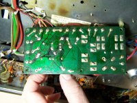
I attached a pic of the back of the p/s board to show the traces, its basically in two halves, the rectifier and 6a fuses supply only the main cap, the rest of it supplies power to other various boards.
I'm waiting to get a list together for another amp before I make a parts order, so I won't have all the parts for a week or so. I found a ham radio shop that has the axial caps for the P/S board, and the rest will hopefully be all in one order.
Its easier to hunt down and get the axial caps than to rig something that's going to possibly be an issue down the road. The board sits very close to the bottom panel, there's no room for any added height, the original 220uF and 330uF caps almost touch the bottom when the board is screwed in place. The wooden base actually has a burnt outline of the components from being so close to the over heated board.
I thought it odd that there's a 6a slow blow fuse on both sides of the rectifier too.
The voltage there when I first checked it with the fuses blown was 14.9v, now with rectifier changed, its just over 24v.
The neg. side fuse only blows when I connect the cap to the amp, not the p/s to the cap. That tells me the cap isn't the issue, besides, the cap passes on both testers I've got.
Its nearly right at its rated value and has a normal looking ESR.
I think the short is in the amp board since that's what I'm disconnecting by leaving that blue wire off.
I attached a pic of the back of the p/s board to show the traces, its basically in two halves, the rectifier and 6a fuses supply only the main cap, the rest of it supplies power to other various boards.
I'm waiting to get a list together for another amp before I make a parts order, so I won't have all the parts for a week or so. I found a ham radio shop that has the axial caps for the P/S board, and the rest will hopefully be all in one order.
Its easier to hunt down and get the axial caps than to rig something that's going to possibly be an issue down the road. The board sits very close to the bottom panel, there's no room for any added height, the original 220uF and 330uF caps almost touch the bottom when the board is screwed in place. The wooden base actually has a burnt outline of the components from being so close to the over heated board.
Attachments
Pass DIY Addict
Joined 2000
Paid Member
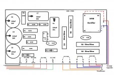
I made a composite image of the top and bottom of the board, maybe this helps a little...
The pair of blue wires on posts #3 and #4 are not what I thought there were. It looks like one wire comes from the transformer (?), is fused, and then goes off into the amp somewhere. It might be worthwhile to track down that set of wires and see where they go - things are not quite so clear from the image. If this comes from the transformer, the AC voltage needs to be rectified somewhere before it is actually useful.
The orange pair is clearly a secondary winding from the transformer that gets rectified with D5 and Q1 is clearly a voltage regulator (though, without a sink which is odd). Searching mouser reveals a "330D regulator" to be a 3v regulator. The ones they have are all surface mount, rather than through-hole, though. Not sure if this voltage reference is correct or not, seems a little low to me. It would be interesting to see what AC voltage is present on this orange set of wires. It would help to know where wires #7-11 go, this would provide some insight on whether 3v is a reasonable power supply for these circuits.
If the fuse pops when you connect outgoing wires to the main PSU cap, then you clearly have a downstream problem - my guess is another shorted cap somewhere on an amp board. This is not, however, evidence that your pain PSU cap is without problems, just that the downstream problem is larger.
Those three blue caps on the right side of the board separate the PSU voltage from ground. As they aged, they shorted and effectively grounded your positive voltage. This created strain on the rectifier and the associated resistors. This is the source of the heat and discoloration.
One thing at a time - this amp can be fixed! It will just take a while, so patience is key.
Attachments
Last edited:
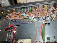
The two blue, two red, and two orange wires all come from the transformer and are different voltages. The blue and red on the left go to the dual cap. The green, red, smaller orange, and pink wires on the right go to various boards. The two black wires are soldered to a ground tab just to the right of the board.
I found a used D330 transistor, and I used two new old caps I had for now in the 100uF positions and two 470uf 100V caps in place of the 330uF caps, and I found a good used 220uF cap. I took the parts from a few junk newer items I had laying around.
That allowed me to put the 4 and 1amp fuses back in. I powered it up without the two 6a fuses.
I added the voltages I have at the p/s board now. The transformer voltages were taken with the wires removed, with no load. The output voltages were with the fuses in place and the unit powered up minus the amp board or 6a fuses. The used rectifier seems to work fine, the numbers are the same as the old one. The transistor came from a small amplified record player, the numbers matched and it tested good so I went with it for now. The larger caps in the axial positions won't allow me to fit the lower cover so they can't stay but for now they got it working. They're 1/3 larger than the original 330uF/50V caps.
With it powered up, I was able to listen to it play through the headphone jack, and was able to use the tape out jacks to run though an old Niles amp with a level control that I've got here on the bench and it plays, the tuner works, the controls all work, but no amp, and no panel lights at all. It appears that every last bulb in this thing is blown. The panel bulbs look like fuses. It seems to me that the only issue keeping this from playing is something on the amp board?
I am getting a faint hum through the headphones though, I didn't hear it though the amp run off the tape out signal though. Not sure what that's coming from, but it seems to go away when I touch the chassis with my hand.
No doubt I'll need to get some proper new caps for the power board but the amp seems to be the main issue.
Attachments
Also, the board that I stole the D330 transistor from had a small bolt on heatsink attached to it, what I did for now was to clip the leads off the shorted transistor and I soldered the new one to the old leads which were already bent forward. This lets the heatsink sit facing away from the board. Its not much but it may be an improvement. Its basically just a 3/8" x 3/4" aluminum finned heatsink attached to the back of the transistor. If it don't clear, i can cut the fins down a bit I suppose. Anything has to be an improvement if it helps get some heat away from the transistor.
Pass DIY Addict
Joined 2000
Paid Member
Finding another D330 regulator was a nice trick! This makes things easier - I was not inspired by what I found on Mouser. Might be useful to carefully measure the output of the voltage regulator - in the event you need to source another one. Having a reading while it is working is very helpful. Retaining the heatsink is also a good idea! It is possible the old part just slowly cooked itself over time. New caps on the PSU board may or may not impact the voltage readings you made, though they will help insure that this board is functioning properly and provide confidence in their longevity.
I don't know what to make of the blue pair of wires that come from the transformer... Seems strange to have a lead out from transformer just for purposes of a fuse, and then have it return to the transformer. One possibility might be that the blue winding is in series with the orange winding to boost the voltages - this would allow Fisher to use a single transformer with multiple receiver models. Might be interesting to see if the orange secondary voltages change with or without that 4A slow blow fuse in place. Do any other wires pop out of the transformer elsewhere?
With a functional power supply, it's just a hide-and-seek game now. Replacing the blue caps should be easy - it looks like each is marked with values. Some of them are probably still "functional" but given the age of the unit, they are all suspect. The orange ones even though they are not marked, all look to be the same size (fairly common in amps). I would pull a few of them to get a measurement, then replace all of them. Be careful to note proper orientation with replacements. The green caps are likely polypropylene/film caps and I would tend to trust them to still be good. Electrolytics first.
If this doesn't restore functionality, I would then go after the small signal transistors on the amp boards.
Another thing to look at might just be a careful inspection/cleaning with an air compressor. Make sure there is nothing stuck or "hiding" under one of the PCBs that might be shorting things out. No telling what might have been dropped in through the cooling vents on the top and slid around a bit. Paperclips, staples, etc.
Thinking about the fuse that blows when you reconnect the wires leading from the main PSU cap to the amp boards, is there more than one wire leading out to other PCBs? Can you disconnect/reconnect them individually to potentially narrow down which board is causing the problem? Anything that provides greater granularity here is helpful...
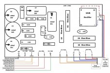
I updated the p/s board diagram to include voltages, and wire destinations.
The rectified voltage is with the 4700uF cap connected but the amp board disconnected.
The amp board is seeing 75.4 volts DC.
The fuses are between the rectifier and the 4700uF cap, not the transformer.
Doing a basic test for resistance to ground, I don't think its a short to ground but a ground short to hot.
If I understand this right, the blue wire from the rectifier, to the 4700uF cap is negative volts DC, this connects to the cap, then splits in two and goes to two pins on the amp board.
As does the red wire. The two blue wires and two red wires connect to the amp board via four pins, if I leave off the first pin, the closest to the cap on the amp board, the dim bulb tester doesn't light and the fuse survives. The fuse that would blow with this connected is on the negative side of the rectifier. The other blue wire connects to a pin on the opposite side of the board. I checked both blue wire pins for a short to chassis ground, and I get 0Ω to ground, but when I check both pins for short to the positive red wire, I get 9877Ω on the right side and 0Ω on the left side. This makes me think that the blue wire is shorted to power on the board somehow. There is no resistance between the blue and red wire's pins on the left side while there is huge resistance on the right side.
With the left side blue wire off, fuses in place, the right channel will play through speakers. So the issue is to find what may be shorting out the left channel side of the rail voltage.
I'm thinking of swapping the modules from side to side to see if the problem switches channels? Is there a simple pin to pin resistance check for one of these STK 082 modules that can be done with the module out of circuit?
Attachments
Last edited by a moderator:
Pass DIY Addict
Joined 2000
Paid Member
Your voltage measures look pretty reasonable - I was expecting to see somewhere from 50-70v on the power supply to the amp boards. You are correct about the polarity of wires here: red is +75v and blue is -75v.
The resistance measures you have of where the red and blue wires hit the PCB provide some interesting insight. Looking at the amp board again, they were nice enough to indicate the traces on the bottom with a silk screen on the top - this makes following the circuit much easier. Looking at where the blue wire connects to the amp board, you have two Rubycon caps right where it hits. The same is true for the red wire - the PCB trace goes directly to a cap. These are my primary suspects for now. Having one functional channel will clearly be an aid in troubleshooting. Most amps run on a biploar power supply like the one you have here. You need a +v, a 0v, and a -v. These are typically joined together in the circuit a +v through a cap to 0v reference (ground) then through another cap to -v. If either of these caps shorts to ground, it places double the voltage across the remaining cap, thus making it more likely to short. For example, each Rubycon cap on the amp board should be rated at 100v with a 75v power supply. But if one cap shorts, then you have ~150 across a cap that is only rated at 100v- so it fails. Now you have both caps shorted, effectively shorting the power supply for the entire channel. If you are lucky, both caps shorted and blew the fuse before the extra voltage on the ground plane blew any of the small-signal transistors on the board. An easy test might be to remove these larger Rubycon caps and see if the short between power supply lines remains on the bad channel.
Swapping the amp ICs is a good experiment to try if they are socketed and easily movable. This will eliminate another variable, though you said they played in another amp, so these aren't a prime suspect right now. With the amp ICs out of the circuit, you have the ability to make another host of resistance measures for comparison that might help you trace things down a little. Check resistance on the pins of the small signal transistors to see how they measure.
Without a data sheet on the amp IC, there is no references for any resistance measurements you might make.
Pass DIY Addict
Joined 2000
Paid Member
My to do list for this would be:
1) swap amp ICs, if this is relatively easy, to make sure both work and your problem stays put. You might want to compare resistance measures across chips - might reveal something. Swapping is likely to be faster, comparing measurements is likely to be safer...
2) Check/remove caps to start tracking down the source of your short in the non-functional channel.
I'm leaning toward just replacing them if I pull them again. To swap them, I just unscrew the modules, then the board and tilt the board over towards the front of the unit. I have a good desoldering gun so removal is easy. Its soldering them back in without accidentally bridging two pins is the hard part. The pins are super close.
I ordered a list of parts so I'm hoping to have most everything this week, it ended up having to come from three different suppliers to get what I needed. The axial caps came from a ham radio repair shop, the caps came from Jameco and the rest from a shop about two hours from me here.
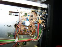
Meanwhile I dug into the display panel a bit to see why the lights were out, it needs all the bulbs, but I found that the indicator lights are in stamped sheetmetal sockets that are badly rusted, the bulb holder and surrounding tin is rusted pretty bad, it looks like acid damage, but only to that immediate area around those indicators?
I ordered a list of parts so I'm hoping to have most everything this week, it ended up having to come from three different suppliers to get what I needed. The axial caps came from a ham radio repair shop, the caps came from Jameco and the rest from a shop about two hours from me here.
Meanwhile I dug into the display panel a bit to see why the lights were out, it needs all the bulbs, but I found that the indicator lights are in stamped sheetmetal sockets that are badly rusted, the bulb holder and surrounding tin is rusted pretty bad, it looks like acid damage, but only to that immediate area around those indicators?
Pass DIY Addict
Joined 2000
Paid Member
Given that the ICs have to be desoldered, I would start with the caps. If you've already removed the ICs, I'd be reluctant to recommend doing so again.
If you have rust, check out a product called "naval jelly" from your local hardware store. Apply a nice coating with a cheap childs paintbrush or Q-tip and let it sit for an hour or two. Be careful not to drip - it removes everything it touches.
If you have rust, check out a product called "naval jelly" from your local hardware store. Apply a nice coating with a cheap childs paintbrush or Q-tip and let it sit for an hour or two. Be careful not to drip - it removes everything it touches.
- Status
- This old topic is closed. If you want to reopen this topic, contact a moderator using the "Report Post" button.
- Home
- Amplifiers
- Solid State
- Sears by Fisher Receiver won't power up