DC offset is simply the DC voltage as seen across the speaker terminals. It should ideally be zero although historically values of up to 100mv (either + or -) were considered acceptable.
The bias current is determined using ohms law from the measured voltage across the known value of 'emitter resistor' connected to the output transistors. On my diagram they are not marked
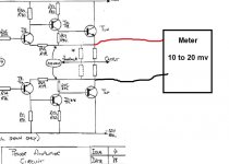
QED say you should see between 10 to 20 millivolts between the two emitters as shown here.
The current limited supply is really to prevent damage when working on a faulty amp. The bias is set at full operating voltage.
The bias current is determined using ohms law from the measured voltage across the known value of 'emitter resistor' connected to the output transistors. On my diagram they are not marked
QED say you should see between 10 to 20 millivolts between the two emitters as shown here.
The current limited supply is really to prevent damage when working on a faulty amp. The bias is set at full operating voltage.
Attachments
There is no risk in checking the bias but do be careful with the meter leads as a slip and accidental short could be disastrous.
I also have concerns over the circuit diagram as drawn as it seems more like a prototype than a fully functional design.
For example the feedback network for the power amp isn't shown, also there is no 'zobel network' on the output, something that is normally an essential for stability.
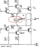
The bias preset (while fully functional as drawn) is configured in a way that is against good practice. If the preset failed or went intermittent then full bias current would be developed, something that could be destructive.
Good practice would have the preset and the resistor below it in reversed positions i.e the resistor at the top and preset at the bottom. Failure of the preset would then give a safe minimum bias current.
I also have concerns over the circuit diagram as drawn as it seems more like a prototype than a fully functional design.
For example the feedback network for the power amp isn't shown, also there is no 'zobel network' on the output, something that is normally an essential for stability.
The bias preset (while fully functional as drawn) is configured in a way that is against good practice. If the preset failed or went intermittent then full bias current would be developed, something that could be destructive.
Good practice would have the preset and the resistor below it in reversed positions i.e the resistor at the top and preset at the bottom. Failure of the preset would then give a safe minimum bias current.
Your meter measures between the two arrow points in the diagram I posted above. Where is says 10-20mv in an oval. That oval will be your meter.
The 1V4 is approximate voltage between the two arrow points when the circuit is operating normally.
Check the voltage but don't turn the preset until you are happy with the method. It can be a fairly fine adjustment and it will vary with temperature.
Check the original unrepaired channel first to see what kind of reading to expect.
Also confirm there is no appreciable DC offset present between the speaker terminals.
Hi again,
just over 0.2V is the lowest reading possible with the pots turned fully anti clockwise, (closed i presume) before i turned them the heatsink was very hot, now it runs very cool. Some of the small resistors around the pots look like thay have got hot at some point. should i check them? thanks
just over 0.2V is the lowest reading possible with the pots turned fully anti clockwise, (closed i presume) before i turned them the heatsink was very hot, now it runs very cool. Some of the small resistors around the pots look like thay have got hot at some point. should i check them? thanks
Its essential you do understand it because you could be dangerously over biased. Under biased is safe, its just the distortion figures that suffer. Over biased runs hot and in more severe cases could enter thermal runaway where the extra heat allows more current to flow... more current more heat... more heat more current and so on until the amplifier fries and fails.
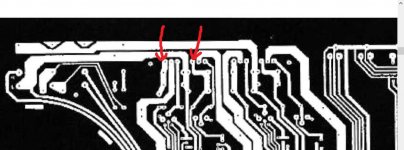
You need to locate these two resistors, and they will be near the output transistors and typically a much larger part than all the others. The marked value will be in the 0.22 to 0.47 ohm region. So very low value.
because you could be dangerously over biased. Under biased is safe, its just the distortion figures that suffer. Over biased runs hot and in more severe cases could enter thermal runaway where the extra heat allows more current to flow... more current more heat... more heat more current and so on until the amplifier fries and fails. You need to locate these two resistors, and they will be near the output transistors and typically a much larger part than all the others. The marked value will be in the 0.22 to 0.47 ohm region. So very low value.
Attachments
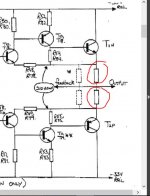
The probes have to measure across the two resistors to get the reading. If you look at the circuit you will see that those points are actually the same as measuring between the two emitters of the output transistors. The emitter is the lead with the arrow. Knowing that should help you locate the correct points.
Now its a critical adjustment and I'll admit its not easy if you are not confident and you are trying to hold leads in one hand while reading a meter and tweaking the pot.
A good method can be to solder wires to the points concerned and bring those wires out to the meter so that you have a good and permanent connection.
Although you need to confirm this I think you are going to be looking at these two points (or same on the other channel).
Attachments
That sounds a realistic value although a little on the low side. Slight movement of the preset will change the reading considerably. Check your original channel in the same way to gauge the factory set value.
Changing the preset will alter the 1.4v slightly but that is not the reading we are interested in and mustn't be used as such.
I'll have to leave it for tonight but remember you are only moving the pot a little and the voltage reading you are interested in will change. If it doesn't seem to work as expected then leave it and we'll go over it again tomorrow.
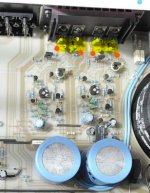
Yes, that seems like the right points to measure the test voltage. The resistors are arranged just as the circuit diagram shows when you include those shown in broken outline.my amp has on each channel 4 large resistors, in parallel pairs, i assume i need to touch the two resistor ends which go to the two outside pins of the pair of output transistors, making sure not touch any the 4 transistor legs in between ??
Below is a pic to make certain we have the right ones and distinguish those in either channel.
PS. Unless the amplifier is working harder (producing output current to a load), turning up the volume control won't do anything. Just let it idle with the cover on.
Attachments
Last edited:
 sounds like you are getting there.
 - Status
- This old topic is closed. If you want to reopen this topic, contact a moderator using the "Report Post" button.
- Home
- Amplifiers
- Solid State
- QED A 240 CD Can Anyone Pls Help With Repair