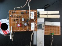
I hand wired this ESP 60-100 Watt amp, very simple but sounds great. The big whoopty-do with this one is it uses amplifying output transistors in Sziklai configuration and is stable. At least the one I built. Only uses a bit over 70ma quiescent current, I'm guessing the stuff other than the complimentary output will use an insignificant draw of current.
I made some substitutions. Q1,2,3,9 are now 2N5551. Q4 is a KSA1220, Q5 is now KSC2690, Q6 KSA1220, Q7 TIP 36C, Q8 TIP 35C.
I also replaced the LED bias reference with three serial 1N914's.
I intend to design a current limit circuit for it, maybe to cut it at 5 amps. I will build a 2nd board and phase inverter to use it in bridge mode where it easily pushes 200 Watts RMS into 8 ohms with a +- 35v DC power supply.
I have a Spyro Gyra cd I use to check clarity, it does symbols, piano and bass with no detectable mud or distortion. Bias seems to stable when it is set at operating temperature. The Q7 to Q8 collector voltage seems to like to be set to 30ma at room temp of about 75°F and after two minutes stops at 50ma.
Yea, not bad, quite a bit like a discrete TDA7294.
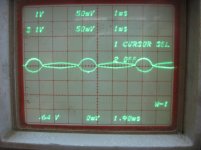
The part I have not figured out yet are the base to ground waveforms of the final output transistors, the TIP 35, 36. Instead of a triangle waveform it is more like an oval. The two are overlaid , one real time and one from storage, not in actual sync. If in sync, it would look like two half circles making a sideways S. Remember that is with a triangle wave input.
Is this peculiar to the Sziklai configuration ? The final output is perfectly shaped as a triangle waveform.
Link to the : 60-80W Power Amplifier
I made some substitutions. Q1,2,3,9 are now 2N5551. Q4 is a KSA1220, Q5 is now KSC2690, Q6 KSA1220, Q7 TIP 36C, Q8 TIP 35C.
I also replaced the LED bias reference with three serial 1N914's.
I intend to design a current limit circuit for it, maybe to cut it at 5 amps. I will build a 2nd board and phase inverter to use it in bridge mode where it easily pushes 200 Watts RMS into 8 ohms with a +- 35v DC power supply.
I have a Spyro Gyra cd I use to check clarity, it does symbols, piano and bass with no detectable mud or distortion. Bias seems to stable when it is set at operating temperature. The Q7 to Q8 collector voltage seems to like to be set to 30ma at room temp of about 75°F and after two minutes stops at 50ma.
Yea, not bad, quite a bit like a discrete TDA7294.
The part I have not figured out yet are the base to ground waveforms of the final output transistors, the TIP 35, 36. Instead of a triangle waveform it is more like an oval. The two are overlaid , one real time and one from storage, not in actual sync. If in sync, it would look like two half circles making a sideways S. Remember that is with a triangle wave input.
Is this peculiar to the Sziklai configuration ? The final output is perfectly shaped as a triangle waveform.
Link to the : 60-80W Power Amplifier
Attachments
Last edited:
I haven't done a real analysis yet but my first guess is the waveform is made by the closed loop system compensating the drive. It is a pure resistor load, an audio test resistor, so reactance is not significant enough to consider for the huge difference in wave shape.
And I left one of the power transistor clamps off to show the trick for a quick medium power test.
And I left one of the power transistor clamps off to show the trick for a quick medium power test.
Last edited:
Right guess. You've understood NegativeFeedBack.my first guess is the waveform is made by the closed loop system compensating the drive.
You can go lower about current bias, you should thermally bind the base spreader to the driver bjts ( not the output bjts), both because of Slizar.
Last edited:
Here's a little clip from the first paragraph of the amp project concerning the bias servo :
Note that there is a major reason that P3A is different from most amp projects you will see on the Net - it uses complementary feedback pairs (aka Sziklai pairs) for the output stage, and quiescent current is controlled by the driver transistors. If the bias servo is mounted on the heatsink, it will provide over-compensation and crossover distortion will result.
Note that there is a major reason that P3A is different from most amp projects you will see on the Net - it uses complementary feedback pairs (aka Sziklai pairs) for the output stage, and quiescent current is controlled by the driver transistors. If the bias servo is mounted on the heatsink, it will provide over-compensation and crossover distortion will result.
Where did you find this ? I do not find it on ESP. It doesn't make sense to me.Here's a little clip from the first paragraph of the amp project concerning the bias servo :
.... quiescent current is controlled by the driver transistors. If the bias servo is mounted on the heatsink, it will provide over-compensation and crossover distortion will result.
Sorry if link to the site didn't show well, I'll re-post it here.
It is in the first block next to the pencil graphic.
60-80W Power Amplifier
It is in the first block next to the pencil graphic.
60-80W Power Amplifier
Here, Elliot mentions not to mount the bias servo ( aka Vbe multiplier, aka bias spreader ) on the heatsink of the output transistors.
The bias current is controlled thru the drivers by the Vbe multiplier, this is where you adjust the trimmer to set the bias, this adjusts the voltage of the Vbe multiplier, the voltage that spreads the bases of the driver bjts.
When the Vbe multiplier is thermally bound to the drivers, by mean of a small independent heatsink, you have a better thermal tracking because you have compensation for the Vbe decrease from temperature increase of the driver bjts. There is no over compensation when on the driver bjts, the over compensation mentioned by Elliot is when on the output bjts.
Sometimes I am so tired I don't see. You said drivers, not output transistors.
Yes maybe that heatsink will not be needed either, the layout is going to make that difficult. I'll keep an eye on it, the servo is closely between Vr1 and Q6, one of the drivers.
So far they barely get above room temp, no heatsink.
I'm using high gain transistors, maybe they won't heat up at all. if so, I'll see if Q5, Q6 heat evenly then connect Q9 to the Q6 heat sink. Or a heatsink for the drivers with a finger that touches Q5.
I'll need to wait until I get a larger power supply, for now I have a +/- 27 volt 2 amp supply.
Last edited:
I have been using this in a subwoofer amp in a small HT.
I use an aluminium sheet as a heatsink for both drivers and On it I have mounted the vbe transistor.
I find that it's running with a very stable bias more than a year now.
You could try the same . Just my 2c.
Regards
Prasi
I use an aluminium sheet as a heatsink for both drivers and On it I have mounted the vbe transistor.
I find that it's running with a very stable bias more than a year now.
You could try the same . Just my 2c.
Regards
Prasi
For sure I'll do that. I will need to make the leads about an inch or a bit longer to reach it.
I built this to learn minute details and it is serving it's purpose.
I do like the fact that it is like the TDA7294. A bit of modification to add overcurrent, over-temp, muting, standby and it could be made on a module like the STK's that fully emulates the TDA7294. But in the meantime as is it can be quickly built to serve some immediate simple purpose.
I see the suppliers only carry a few hundred of the TDA7294, 7293 and it is getting old, probably not being used in many new designs. Class D is obviously the new trend, but I like the analog function, that real time proportional action pleases me.
I deleted a post that mentioned that the MJW output transistors sounded a bit brassy compared to the TIP35C TIP36C pair. I guess wrong, I switched from a relatively brassy POD-4112 test speaker to a Sony SS-B1000 and on the MJW3281A (NPN) MJW1302A (PNP) pair the sound changed to excellent, smooth, no brassy highs but a bit attenuated in the 5khz range.
I suppose then this would say the older TIP's with an Ft of 3mhz must not be amplifying the highs as well as the MJW's. I'll stick with the MJW's since they seem to work better with better speakers.
I suppose then this would say the older TIP's with an Ft of 3mhz must not be amplifying the highs as well as the MJW's. I'll stick with the MJW's since they seem to work better with better speakers.
I think, as you might expect with harmonic distortion, the older general purpose power transistors of the 2N3055 family will produce a lot more of it compared to modern power transistors developed specifically for audio. In other words, their linearity is poor, particularly at higher power. You can read a chapter on this topic in any edition of Doug Self's audio power amplifier design handbook but most authors also make a clear point of it.
If you can manipulate that distortion in some way that is pleasant to the ear, that's fine but with most simple class AB designs like this, you need to use the best available types for the output stage and On-semi's MJL, MJW, NJW series is up there and affordable.
I listened recently to a friend's P3a in which he used some fake Sanken LAPTs (2SC2922/A1216). It sounded like something your kids might be happy to play with but not something you'd like to use for your favourite music. Then the genuine parts were fitted - oh my, what a transformation! I wanted to listen to a lot more that evening.
When you make comparisons of particular speakers combined with the amplifier, you are out of my territory but I can certainly agree with your other findings about semis - enjoy") .
.
Regarding the location of Q9, on the current PCB pic in Rod Elliott's article, it's shown cable-tied to Q6. There's no easy way to screw that up, as there could be with some of the PCB layout attempts I've seen here on the forum.
If you can manipulate that distortion in some way that is pleasant to the ear, that's fine but with most simple class AB designs like this, you need to use the best available types for the output stage and On-semi's MJL, MJW, NJW series is up there and affordable.
I listened recently to a friend's P3a in which he used some fake Sanken LAPTs (2SC2922/A1216). It sounded like something your kids might be happy to play with but not something you'd like to use for your favourite music. Then the genuine parts were fitted - oh my, what a transformation! I wanted to listen to a lot more that evening.
When you make comparisons of particular speakers combined with the amplifier, you are out of my territory but I can certainly agree with your other findings about semis - enjoy
. Regarding the location of Q9, on the current PCB pic in Rod Elliott's article, it's shown cable-tied to Q6. There's no easy way to screw that up, as there could be with some of the PCB layout attempts I've seen here on the forum.
Last edited:
I'm going to link that bias servo for prolonged high power operation but for now even at levels that produce slight ear discomfort it stays at 50mv between Q7, Q8 collector and the power transistor heat sink about 110°F. But before I start using it for a bass amp that hot finger will be done between Q9-Q6.
I am thrilled to unknowingly prove those claims of refined audio transistors. So they are not only the same designs with a different part number.
I also walked in the tracks of those who discovered fake lateral MOSFETS. A lot of theory review and calculations led me to the undisputable fact that I was sold vertical mosfets marked as audio grade fet's. Even after all my years I don't know everything. I knew some fets had different pin configurations but not why. Had I known, I would have instantly recognized the mosfet type and missed out on the excellent review and additional learning experience I was blessed with. LOL yes, I learned more on the junk than if I had simply built it and it worked. Again, my whole objective is to learn and end up with a pretty decent amp as a reward.
I do not have the time or resources to design an amp for sale.
I feel satisfied with ESP and appreciate the excellent resource pages. I'm thinking I will sometime in a few months order the equalizer board for it. His prices are fair but the shipping cost kills the want for a small order. Not his fault. It would be a good idea for him to find a fulfillment center in the US to lower shipping cost. In case you're reading Rod, look into that.
Last edited:
I finally broke down and built a two band equalizer for a test and even that was a significant improvement. As a matter of fact I think a two band eq could be smoother across the band than a low count eq such as a five or even 10 band. Unless the Q is variable and easily bridged between poles they have a scalloped response curve across the audio band. Maybe it starts getting good with a 31 band.
The eq is in TI's AND8177, figure 20. The input is incorrectly shown as pin 3 non inverting but is obviously wrong. It barely has any effect as shown, and since most all other filters I see, are fed to the inverting input so I switched it to the inverting input.
Now it obviously has +/- 20db of effect. The best two band tone control I have heard so far.
This circuit is only compatible with an NE5532 or equivalent.
Last edited:
...The eq is in TI's AND8177, figure 20. The input is incorrectly shown as pin 3 non inverting but is obviously wrong....
This circuit is only compatible with an NE5532 or equivalent.
Why "only NE5532"??
That's not even what the Figure says. (Which is odd considering the App Note is supposed to sell the NE5532/4.) I have not seen a NE531 in, I do not remember when. The alternate "301" *with unity gain compensation* is essentially a '741. (OK, in -1 work a '301 may be twice as fast as a '741, big deal.) This plan with minor value changes is pretty much "all" hi-fi bass-treble tone controls, and goes back to Baxandall and pentodes.
Also note "Base". Nobody at the factory has actually looked at this AppNote in a very long time. It just gets handed down as each company takes over the business.
The 68K gives correct DC balance for the high-current NE5xxx chips, but adds hiss, so should be bypassed. With no-current JFET amps like TL072 no resistor is wanted (strap to ground).
Attachments
I tried a TL082 in it and it sounded awful, probably designed for BJT inputs, JFET inputs must not respond well to something about it. I had intent to run the circuit in a sim and swap types but need to review how to use the sim, haven't used one for years.
Maybe the one order less distortion of the NE5532 makes it better for filters. Also in this design, some caps and resistors have swapped positions from typical tone control designs.
The caps often connect the pot wiper to the input rather than resistors in typical designs. So maybe the swap puts stress on some op amps that they can't drive well, but the NE5532 wins in that configuration. So yes the design could be a selling point for NE5532's.
I wonder how many people made that circuit with the swapped inputs and gave up right away without learning about how a filter works ? Sorry if I goofed.
Last edited:
I had various oscillation problems with the NE5532 that change with the amplitude of the tone controls. No oscillation with the volume control 75% and up. Replace it with the TL084 and no oscillations but a harsh sort of sound. (I have heard others say the TL084 is harsh also) I may try a bandwidth limit on the input buffer or get some TL072's and hear how they sound.
It only has a gain of 4.3, since I can't find details on the NE5532, may need to use a different amp with more docs or as above try that bandwidth reduction and/or a phase lag circuit.
No such problems with the LME series TI audio amps. Nor harshness.
It only has a gain of 4.3, since I can't find details on the NE5532, may need to use a different amp with more docs or as above try that bandwidth reduction and/or a phase lag circuit.
No such problems with the LME series TI audio amps. Nor harshness.
Input noise with a guitar now. That TL082 almost made me give up on this amp until I remembered switching chips. But now I take the cd and play it on my RCA Pro receiver and it is sooo crystal clear I did wanted to trash this amp. It's horrible. Some tinny sort of buzz to it that is unpleasant, at least until I try a better input and EQ chip.
I'm going to move away from this amp for awhile. Take a break from stress. Those tiny buzz click problems can really be frustrating. The scope probe isn't much help either, it changes the sound when in some parts of the circuit.
So now after this I will know more about front ends. I had been concentrating on amps. I see the front end is no quick and easy thing. It needs lots of focus on precision and above that , noise control.
- Status
- This old topic is closed. If you want to reopen this topic, contact a moderator using the "Report Post" button.
- Home
- Amplifiers
- Solid State
- My New Build, ESP 60-100 Watt