I have now tested circuit on breadboard with led indicators at relays. led's were always on to start with so I connected 500k resistors from opamp inputs to earth as these were floating. Had to change reference voltage at opamps to give 0.25v and -0.25v.
This sets sensing dc voltage at approx 0.7v and circuit works fine.
I updated spice circuit and tested inputs at 2hz which I understand is lowest frequency on a CD recording. Works okay between 0 and 0.6v dc input but at around 0.7v dc the relay output oscillates ON/OFF at 2hz.
Its the sine wave residue after the two pole filter interacting with the opamp comparator. Above 0.8vdc the relay output is stable.
I am sure this would happen on any low pass filter sensing system when the transistors turn on and off. With a single pole filter the oscillation covers a larger range so I don't understand why some articles say a two pole filter is not so good as a single pole.
In practice I would think that at failure the dc offset would be the supply rail voltage so I will be building this circuit in a separate case.
The downside to this is that I will have 6 speaker leads from the main amp to this case and another 6 leads from the case to the speakers plus power leads.
The next amp build if this one is okay will house all the amps and speaker offset systems in one case.
DC Detect
oldjack,
The problem with anyone's design for DC protection is compromise. Use more than a single pole and the charge time (i.e. detect time) goes up. Use any diode or bridge, you are counting on forward leakage for DC levels, without them you have whole new problems. You need a resistor on the input, more than likely + side, opamp/comparator to control input bias, which then changes the trip level. There are other design issues. Any design that will disconnect the speakers when something bad happens is a good thing to have.
MI
PS I redesigned my DC Detector again. I believe this will be the one.
Attachments
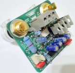
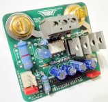
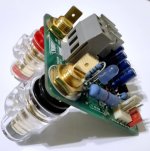
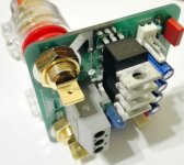
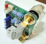
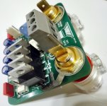
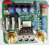
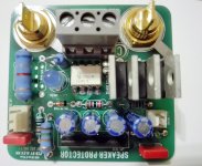
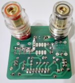
My speaker protector use old specialized IC uPC 1237 HA combined with ASSR 621 and power MOSFET .")
Attachments
-
 IMG_20171128_201709.jpg345.2 KB · Views: 443
 -
 IMG_20171128_201715.jpg416.3 KB · Views: 414
 -
 IMG_20171128_201725.jpg436 KB · Views: 364
 -
 IMG_20171128_201754.jpg407.7 KB · Views: 353
 -
 IMG_20171128_201804.jpg435.4 KB · Views: 111
 -
 IMG_20171128_201812.jpg493.5 KB · Views: 114
 -
 IMG_20171128_201822.jpg626.4 KB · Views: 147
 -
 IMG_20171128_201827.jpg657.6 KB · Views: 169
 -
 IMG_20171128_201855.jpg411.4 KB · Views: 174
MI
Yes the delay time does increase using a 2 pole filter, I could see the delay on the test circuit between the dc voltage input and the led's operating. It was probably near 1 sec.
Not sure how long a speaker can withstand the dc voltage?
I will test the circuit again using a single pole filter; I think when I simulate using spice it probably does not reflect what actually happens in practice.
I see on your circuit you are using comparators; its not a lot different from mine.
Do the comparators reduce the delay time much compared to opamps.
MI
Yes the delay time does increase using a 2 pole filter, I could see the delay on the test circuit between the dc voltage input and the led's operating. It was probably near 1 sec.
1 second, is too long.
Not sure how long a speaker can withstand the dc voltage?
If its wound from 4 gauge wire, probably along time. Most are not, rail fuses will go, but you don't want that much time to pass, get the trip time as short as you can.
I will test the circuit again using a single pole filter; I think when I simulate using spice it probably does not reflect what actually happens in practice.
I see on your circuit you are using comparators; its not a lot different from mine.
Do the comparators reduce the delay time much compared to opamps.
The problem with opamps in open loop is numerous, latch-up, unpredictable outcomes, input bias, etc. Comparators run open loop which makes them faster, but the problem I don't like is they're open collector/drain, unless you want to spend a lot more, so I have to deal with the -5 to +5 v output to my MCU. Your LT1001 has high open loop it should be just as fast. Run your simulation and look at DC levels at C2 and C3 with just 5 vDC and then 50 vDC watch how long each takes to get to over 800mv your trip point.
Later,
MI
Its a balancing act.
Not so long the voice coil starts to burn.
But not so short you get nuisance drop outs on high power low frequencies.
I set mine to 500mS.
I just a very simple PIC micro based solution.
I drop the amplifier output down using 10k voltage dividers straight into PIC I/o pins.
I use one pin for each phase.
The output is to a relay using a transistor driver.
An externally hosted image should be here but it was not working when we last tested it.
Last edited:
I just a very simple PIC micro based solution.
I drop the amplifier output down using 10k voltage dividers straight into PIC I/o pins.
I use one pin for each phase.
The output is to a relay using a transistor driver.
How much voltage can a PIC I/O take? I've never used any.
MI
How much voltage can a PIC I/O take? I've never used any.
MI
I think a PIC will tolerate up to about 25mA.
So 25mA through a 10k resistor is +/- 250 volts peak max.
MI
I tested single pole LP filter both on spice and on breadboard.
For my Mid Frequency and High Frequency amps it works fine as they will be working above 300hz. For the Low frequency amp there could be a problem at around 5hz and below without any dc, it caused oscillation of output with led's flashing at input frequency.
Even with a 2 pole filter there could be some problems at low frequencies.
So I need to be more confident of the design before I build it.
On another problem concerning the relays with fused contacts I had an idea.
If dc voltage is input to a speaker is it the high current with it that causes the burn out due to no change in inductance at the speaker coil?
The reason I ask is that I have regulated power supplies for the MF and HF amps but with conventional PS supplies for the LF amp; however for the next tri-amp I will be using regulated power supplies throughout, each with a current limiter and I was thinking whether I could fit a Solid State Relay with resistor to change either the current limit and/or the voltage output but not sure what the response time of the regulators would be.
Hi Alex
Not sure if the protector is still made.
I would like to carry on with my current design until I feel confident it will work.
From what I can see, the old protection circuits are not made any more so I would feel happier with a discrete type of design where I can be sure of buying the parts.
Not sure if the protector is still made.
I would like to carry on with my current design until I feel confident it will work.
From what I can see, the old protection circuits are not made any more so I would feel happier with a discrete type of design where I can be sure of buying the parts.
MI
For the Low frequency amp there could be a problem at around 5hz and below without any dc, it caused oscillation of output with led's flashing at input frequency.
Even with a 2 pole filter there could be some problems at low frequencies.
So I need to be more confident of the design before I build it.
I personally would not waste energy with anything below 18Hz.
On another problem concerning the relays with fused contacts I had an idea.
If dc voltage is input to a speaker is it the high current with it that causes the burn out due to no change in inductance at the speaker coil?
Depending on the rail voltage and the speakers actual resistance, you are looking at a huge amount of current, relays don't do well with this.
MI
Depending on the rail voltage and the speakers actual resistance, you are looking at a huge amount of current, relays don't do well with this.
MI
I put 100nF capacitor across the relay contacts to soak up any arcing or to at least help.
I use a 20 amp relay but use both pairs of contacts in parallel to up the rating.
Hi Alex
Not sure if the protector is still made.
I would like to carry on with my current design until I feel confident it will work.
From what I can see, the old protection circuits are not made any more so I would feel happier with a discrete type of design where I can be sure of buying the parts.
Your point of view it's correct , got it
I have 10 pieces from UTsource and I will test soon ! Thanks for comments .MI
The reason I mentioned 5hz was that I understand cd's can reproduce frequencies at or below 5hz and without any dc this caused the opamps to trigger on spice using a single pole filter and also but not as bad with a two pole filter.
As I have not built a dc protection system before I am open to advice.
With the current limiters on the voltage regulators my design would restrict I on each of the +ve and -ve supplies:
HF am 28v, 1.5a/-28v, 1.5a
MF amp 32v, 1.5a/-32v, 1.5a
LF amp 36v, 2a/-36v, 2a
So with dc short to speaker I would expect initial dc to be max 1.5a (HF and MF), 2a (LF).
My earlier idea was to fit additional control resistor to each regulator with SSR so that if dc was sensed the output voltage would be dropped to around 5v still with current limit.
I could ask one of the speaker suppliers such as Scanspeak what dc their speakers would take and for how long.
MI
The reason I mentioned 5hz was that I understand cd's can reproduce frequencies at or below 5hz and without any dc this caused the opamps to trigger on spice using a single pole filter and also but not as bad with a two pole filter.
oldjack
You need to let go of the low frequencies, you can't hear 5 Hz, even though technically a CD can go to 0Hz(DC), I don't think any CD player would allow this, the best a human has done in a lab is 12-14Hz, a much younger me could hear to 16-17 Hz tested in my living room with gen. and subwoofer. You don't want 5Hz at high power hitting your subs, not good hearing the speaker cone hit its end stops, trust me I have.
With the current limiters on the voltage regulators my design would restrict I on each of the +ve and -ve supplies:
HF am 28v, 1.5a/-28v, 1.5a
MF amp 32v, 1.5a/-32v, 1.5a
LF amp 36v, 2a/-36v, 2a
So with dc short to speaker I would expect initial dc to be max 1.5a (HF and MF), 2a (LF).
My earlier idea was to fit additional control resistor to each regulator with SSR so that if dc was sensed the output voltage would be dropped to around 5v still with current limit.
The best outcome, even with current limiting, would be to shut it down. No need to heat the speaker coil up.
MI
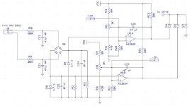
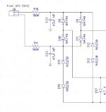
I have decided to go ahead with clamping the voltage across the low pass filter capacitor 47uf so I can use a lower voltage bi-polar instead of a higher voltage one to cover amps with high rail voltages. Here is the latest input filter. I'm also going with discrete diodes instead of a bridge. I basically want to harden the controller against catastrophic failures.
MI
MI
Attachments
MI,
What supply voltage are you using? The Bipolar caps seem to be limited to 50v and the panasonic range only have a projected life of 2000 hrs.
I will be using two standard electrolytics back to back.
I have been doing some more testing with the filters, on spice I found that a 2 pole filter with 100k/10uf 1st stage and 100k/5uf 2nd stage gave much better performance than 100k/47uf single pole. Response time with the breadboard was also better.
Looks like that to do an accurate check for delay time I will have to do some calcs using transfer functions which is likely to take me ages!!
I intend to use thyristors to activate the relays so that the relays will be latched open after the dc signal is sensed. Also will have led indication for each amp if fault occurs with manual reset button across the thyristors.
Each relay will have a dedicated thyristor.
I have started to design the pcb's with autocad; in my case I have to accommodate 3 pairs of amps. I was looking at pcb mounted relays but may go for separate relays in case of replacement.
- Status
- This old topic is closed. If you want to reopen this topic, contact a moderator using the "Report Post" button.
- Home
- Amplifiers
- Solid State
- Speaker Protection Using Optoisolator