I would like to add speaker protection for my TriAmp especially as there will be direct connections between the amplifiers and the speakers.
I understand using a low pass filter from the amp outputs but the rest of the circuit look quite complicated. I have three stereo amplifiers so it adds up to quite a lot of circuits.
Could I use optoisolators (led + phototransistor), with two units connected to the LP filter output, one wired normally and one wired in reverse for any negative DC. The other sides of the optoisolators would then switch relays off.
In my case these would be downstream of the linear voltage regulators (LM338 for +Ve and LT1033 for -Ve). The circuits I think should sense at around the LED forward volt drop plus in circuit resistor volt drop.
You could use opto's but since the signal is ground referenced (to the speaker return) you don't need to. any transistor would do. Peavey trips their circuit at 7 vdc for too long . The bidirectional sense is important - you can use two zener diodes and two transistors, back to back or a diac or sbs which breaks down either way. The two transistors in different directions need to go to one transistor to drive the relay coil, since it is uni-polar. This is usually done through a wire or circuit. If either senses the relay opens. See various protection circuits on solid state.
More modern and more trouble free than relays (which are not sold to break DC current typically) are nmos fet's. Two of these are cheaper than most hard contact relays, too. See those protection circuits.
More modern and more trouble free than relays (which are not sold to break DC current typically) are nmos fet's. Two of these are cheaper than most hard contact relays, too. See those protection circuits.
I used a PIC micro for sensing the signal to the speaker.
I put a 10k resistors in series and another to ground onto the PIC pin.
This makes it see the signal if it goes above 4 volts or below -4 volts.
If the signal is there for more than 100mS the relay is turned off.
It also gives a four second delay on power up.
Its not the most difficult PIC program I have written.
opto works really well. I used them for speaker protection in car amp that drove an scr that shut down the power supply until the head unit was switched off then on.
worked on both DC and HF > 20khz signals. HA11A1 is the AC input ( 2 photo diodes ) version I believe
worked on both DC and HF > 20khz signals. HA11A1 is the AC input ( 2 photo diodes ) version I believe
Last edited:
opto works really well. I used them for speaker protection in car amp that drove an scr that shut down the power supply until the head unit was switched off then on.
worked on both DC and HF > 20khz signals.
I use them in a irs2092 class d amp to control the chip reset pin.
It allows me to reference the pic off B- while controlling reset at 0 to 5 volts.
You could use opto's but since the signal is ground referenced (to the speaker return) you don't need to. any transistor would do. .
Yes. My only reason to use optos, that my amplifier is dual mono, with separated ground, and I found it more elegant way, instead of of 2 separated housekeeping PSU.
Anyway optos are elegant solution for bridged amps too...
Sajti
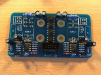
I use opto's driving a pair of big mosfets as a solid state relay (RdsON <10m). Over current sense (trip at 20A) is a resistor divider across an inverse pair of (additional) opto's. Op amp comparitors check for DC Out and apply power-up (and down) mute etc as well. Operates on the high side to protect against a short to ground (which a low side switch cannot do). One SSR on each channel and if one trips the other is forced off too. Yell if you want a circuit diagram for ideas. I have had them rendered as pair of small PCB's from a local (Malaysia) supplier as well.
My philosophy being that I can't really protect my output transistors but with a hundred milliohms in series I can protect my precious speakers.
My philosophy being that I can't really protect my output transistors but with a hundred milliohms in series I can protect my precious speakers.
Thanks for the replies; I will carry on down the optoisolator route.
My main problem is that I built the triamp and it fills two large cases, one for power supplies and one for the amps, filter and attenuators so there is very little room left for anything else but will somehow fit them in.
My main problem is that I built the triamp and it fills two large cases, one for power supplies and one for the amps, filter and attenuators so there is very little room left for anything else but will somehow fit them in.
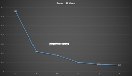
My DC protection working time (vertical axis) vs amplifier output DC voltage (horizontal axis). I use Omron G2RL2 relay, the 2 sections connected parallel. Measured resistance of it is 2,5mohms. Measured with 5A AC current. This is quite consistent, I measured 7 circuit, 2.4-2.5mohms.
Sajti
Sajti
Attachments
Very interesting Sajti, again as with Johno's circuit quite involved, two very different solutions, both with a lot of design input.
I was trying to keep my method very simple as the triamp took me ages to design and build with a lot of mistakes along the way and now that it works really well I just wanted to finish off the amp and speaker protection. Being a triamp every modification is times 3.
I was trying to keep my method very simple as the triamp took me ages to design and build with a lot of mistakes along the way and now that it works really well I just wanted to finish off the amp and speaker protection. Being a triamp every modification is times 3.
This is worth reading, lots of useful information Loudspeaker Protection and Muting
Thanks, I had read Elliot Sound Products info before and this was why I looked at two optoisolators instead of the diodes and transistors, but the circuit size would probably be the same; so I would need three of these circuits and six output relays.
At the moment I am using four old kef coda7 speaker cabinets and two older cabinets to make up the speaker system as the crossovers are still inside, but when I eventually (!!) build new cabinets I will need to have the protection in place.
At the moment I am using four old kef coda7 speaker cabinets and two older cabinets to make up the speaker system as the crossovers are still inside, but when I eventually (!!) build new cabinets I will need to have the protection in place.
")
Hi Tromperie, yes the power down mute, power up mute, DC detect, over-current detect and the use of the opto triac as a latch are all mine and original. Just reflects the stuff I have in my parts collection.
Some time ago I purchased the DIY protection boards but with closer understanding of how it worked I felt it was not complete nor symetrical (plus the idea of a relay breaking large direct currents is crazy) and thus built my own version along the lines of the uPC1237.
The idea of the opto mosfet trigger came from Kean Token if I recall correctly. A really elegant use of technology if I may say.
Hi Tromperie, yes the power down mute, power up mute, DC detect, over-current detect and the use of the opto triac as a latch are all mine and original. Just reflects the stuff I have in my parts collection.
Some time ago I purchased the DIY protection boards but with closer understanding of how it worked I felt it was not complete nor symetrical (plus the idea of a relay breaking large direct currents is crazy) and thus built my own version along the lines of the uPC1237.
The idea of the opto mosfet trigger came from Kean Token if I recall correctly. A really elegant use of technology if I may say.
Dear Johno,
Did you design a PCB for this board ? Any spare PCBs or files available ? A little explanation of the various functions of the modules ? Thanking you !
--gannaji
- Status
- This old topic is closed. If you want to reopen this topic, contact a moderator using the "Report Post" button.
- Home
- Amplifiers
- Solid State
- Speaker Protection Using Optoisolator